background image

Dealing with hardware faults

99

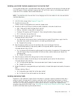
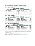
Diagnostic steps for replication setup

The tables in this subsection show menu navigation for virtual replication using the SMC.

Can you successfully use the replication feature?

Answer Possible reasons

Action

Yes

System functioning properly.

No action required.

No

The replication feature is not licensed 
on each controller enclosure used for 
replication.

Verify licensing of the optional feature per system:

In the 

Home

 topic in the SMC, select 

Action > Install License

.

The License Settings panel opens and displays information 
about each licensed feature.

If the replication feature is not enabled, obtain and install a 
valid license for this feature.

See the Storage Management Guide for license information.

NOTE:

Replication is not supported by SAS controller enclosures. 

Compatible firmware revision 
supporting the replication feature is not 
running on each system used for 
replication.

Perform the following actions on each system used for virtual 
replication:

In the 

System

 topic, select 

Action > Update Firmware

.

The Update Firmware panel opens. The Update Controller 
Modules tab shows firmware versions installed in each 
controller.

If necessary, update the controller module firmware to ensure 
compatibility with the other systems.

For more information on compatible firmware, see the topic 
about updating firmware in the Storage Management Guide.

Invalid cabling connection.
(If multiple enclosures are used, check 
the cabling for each system.)

Verify controller enclosure cabling:

Verify use of proper cables.

Verify proper cabling paths for host connections.

Verify cabling paths between replication ports and switches are 
visible to one another.

Verify that cable connections are securely fastened.

Inspect cables for damage and replace if necessary.

No

A system does not have a pool 
configured.

Configure each system to have a storage pool.

Table 23

Diagnostics for replication setup: Using the replication feature

Summary of Contents for RealStor 4005 Series

Page 1: ...setup for Seagate 5005 4005 Series enclosures It also describes removal and installation of customer replaceable units for these enclosures The document is intended for use by storage system administ...

Page 2: ...data rates may vary depending on operating environment and other factors The export or re export of Seagate hardware or software is regulated by the U S Department of Commerce Bureau of Industry and...

Page 3: ...U12 23 2U24 23 5U84 23 2U enclosure core product 24 2U enclosure front panel 24 2U enclosure rear panel 25 2U enclosure chassis 27 5U enclosure core product 28 5U enclosure front panel 29 5U enclosure...

Page 4: ...on 61 Testing enclosure connections 61 Grounding checks 61 Host system requirements 62 Cabling considerations 62 Connecting the enclosure to hosts 62 CNC technology 63 SAS protocol 64 Host connection...

Page 5: ...eshooting 2U enclosures 89 PCM Faults 90 Thermal monitoring and control 90 Thermal alarm 90 Troubleshooting 5U enclosures 91 Thermal considerations 91 USB CLI port connection 91 Fault isolation method...

Page 6: ...opping I O 118 Shutting down a controller module 118 Removing an IOM 119 Installing an IOM 121 Verifying component operation 121 Replacing a 2U storage enclosure chassis 122 Before you begin 122 Verif...

Page 7: ...dards and regulations 142 International standards 142 Potential for radio frequency interference 142 European regulations 142 Safety compliance 142 EMC compliance 142 AC power cords 143 Recycling of W...

Page 8: ...AS 30 22 5U84 expansion enclosure rear panel components 31 23 Power supply unit PSU detail 31 24 Fan cooling module FCM detail 32 25 Drawer bezel details 33 26 LEDs Ops panel 2U enclosure front panel...

Page 9: ...location 76 66 Connecting two 5005 4005 Series 5U storage systems for replication multiple servers one switch one location 76 67 Connecting two 5005 4005 Series 2U storage systems for replication mul...

Page 10: ...Figures 100 Removing an IOM 1 of 2 134 101 Removing an IOM 2 of 2 135 102 USB device connection CLI port 144 103 Install a qualified SFP option into a 5005 or 4005 Series FC iSCSI controller module 1...

Page 11: ...00 25 Diagnostics for replication setup Replicating a volume 100 26 Diagnostics for replication setup Checking for a successful replication 101 27 5005 Series enclosure models 102 28 4005 Series enclo...

Page 12: ...t configuration characteristics for controller and optional expansion enclosures 5005 4005 Series supports 2U and 5U chassis form factors that are configurable as either an RBOD or an EBOD 5005 4005 S...

Page 13: ...tion TIP See the CLI Reference Guide for information about configuring CNC ports with host interface protocols of the same type or a combination of types CNC controller modules ship with CNC ports ini...

Page 14: ...ng the web interface to configure and manage the product Storage Management Guide Using the command line interface CLI to configure and manage the product CLI Reference Guide Event codes and recommend...

Page 15: ...Document conventions and symbols 15 IMPORTANT Provides clarifying information or specific instructions NOTE Provides additional information TIP Provides helpful hints and shortcuts...

Page 16: ...o Figure 25 page 33 Use a minimum of three people to lift the enclosure using the lifting straps provided Avoid lifting the enclosure using the handles on any of the CRUs because they are not designed...

Page 17: ...ust be grounded before applying power The plug on the power supply cord is used as the main disconnect device Ensure that the socket outlets are located near the equipment and are easily accessible 2U...

Page 18: ...rotection for the enclosure and must not be overloaded by the total number of enclosures installed in the rack When addressing these concerns consideration should be given to the electrical power cons...

Page 19: ...ater when the storage system is either idle or aging and continuing to receive new I O data the controller writes the data to the disks Read ahead caching The controller detects sequential data access...

Page 20: ...supercapacitor pack the Cache Status LED blinks at a rate of 1 10 second on and 9 10 second off See also Cache Status LED details page 43 NOTE Please refer to Enclosure variants page 23 for details ab...

Page 21: ...age 23 for details about various 2U24 enclosure options Figure 3 2U24 enclosure system dimetric front orientation Figure 4 2U24 enclosure system dimetric rear orientation The 2U24 controller enclosure...

Page 22: ...23 for details about various 5U84 enclosure options Figure 5 5U84 enclosure system dimetric front orientation Figure 6 5U84 enclosure system dimetric rear orientation The 5U84 controller enclosure abo...

Page 23: ...ndant PCMs must be compatible modules of the same type both AC 2 Supported controller module IOMs include 4 port FC iSCSI and 4 port HD mini SAS Supported expansion module IOMs are used in expansion e...

Page 24: ...g An enclosure chassis which includes the midplane PCB and an integral operator s Ops panel that is mounted on the left ear flange at the front of the enclosure Two 580W 100 240V AC power cooling modu...

Page 25: ...onents 2U rear panel components Controller modules The top slot for holding IOMs is A and the bottom slot is B The face plate details of the IOMs show the modules aligned for use in A In this orientat...

Page 26: ...s Figure 14 Expansion module detail J1212 J1224 J1284 IMPORTANT RBOD EBOD configurations When the expansion module shown above Figure 14 is used with 5005 4005 Series controller modules for adding sto...

Page 27: ...chassis with midplane see Figure 17 page 28 The chassis has a 19 inch rack mounting that enables it to be installed onto standard 19 inch racks and uses two EIA units of rack space 3 5 for a 2U enclos...

Page 28: ...is based on an enclosure subsystem together with a set of plug in modules A typical enclosure system as supplied includes the following An enclosure chassis consisting of Two sliding drawers for hold...

Page 29: ...enclosure all PSU slots cooling module slots and IOM slots must contain a functioning CRU Do not replace a faulty CRU until the replacement is available in hand 5U enclosure front panel Figure 18 5U84...

Page 30: ...performed by qualified service personnel only Contact your service provider for more information 5U enclosure rear panel Numeric designators on PSUs and FCMs and alphabetic designators on IOMs indica...

Page 31: ...er enclosures and optional 5U expansion enclosures Figure 23 Power supply unit PSU detail The 2U enclosures use a redundant PCM that integrates a power supply and cooling fan within the same CRU modul...

Page 32: ...drawer provides access to 42 slots for Disk Drive in Carrier DDIC modules DDICs are top mounted into the drawers as shown in the drawer diagram on page 29 The front of the enclosure also provides encl...

Page 33: ...f each drawer Figure 25 Drawer bezel details NOTE Figure 25 shows symmetrical drawer bezel details The callouts provided on the right side detail also pertain to the left side detail Operator s Ops pa...

Page 34: ...e used to provide feedback to the user Its primary function is to display an enclosure unit identification number to assist users in setting and maintaining multiple enclosure systems Thermal sensor T...

Page 35: ...LED displays green when system power is available operational Module Fault LED amber LED illuminates when experiencing a system hardware fault It may be associated with a Fault LED on a PSU FCM IOM DD...

Page 36: ...nput frequency The dimetric rear orientation in Figure 28 shows the PCM aligned for insertion into the right hand PCM slot located on the enclosure rear panel Figure 28 LEDs 580W PCM 2U enclosure rear...

Page 37: ...unit 5U enclosures Power is provided by two 2 214W PSUs The PSU voltage operating range is nominally 200V 240V AC and operates at 50 60 Hz input frequency The dimetric rear orientation in Figure 28 s...

Page 38: ...o minutes of the removal of the defective module Verify that you have a replacement module on hand before removing the defective FCM Figure 30 LEDs FCM 5U enclosure rear panel NOTE The System airflow...

Page 39: ...of the partner SBB module s and vice versa within the enclosure An enclosure system alarm occurs when incompatible configurations are detected 12Gb s controller module LEDs The diagrams with tables t...

Page 40: ...oting Off The controller module is not OK or is powered off 4 Fault Off The controller is operating normally Amber A fault has been detected or a service action is required Blinking amber Hardware con...

Page 41: ...Fault Off The controller is operating normally Amber A fault has been detected or a service action is required Blinking amber Hardware controlled power up or a cache flush or restore error 5 OK to Rem...

Page 42: ...fault has been detected or a service action is required Blinking amber Hardware controlled power up or a cache flush or restore error 4 OK to Remove Off The controller is not prepared for removal Blu...

Page 43: ...he typical host I O time out of 60 seconds at which point system failure would cause host application failure If primary power is restored after the backup power is depleted the system boots and resto...

Page 44: ...ots The system is flushing data to CompactFlash If the problem persists replace the controller module Yes at a blink 1 1 rate 2 Hz and the controller does not boot You may need to replace the controll...

Page 45: ...carrier adapter is available to accommodate 2 5 disk drives Each 2U24 drive slot holds a single low profile 5 8 inch high 2 5 inch form factor disk drive in its carrier The disk drives are vertical T...

Page 46: ...illustrations Modules are shown oriented for insertion into disk drive slots located on the enclosure front panel Figure 36 Dual path LFF 3 5 disk drive carrier modules Figure 37 Dual path SFF 2 5 dr...

Page 47: ...r modules also known as drive blanks are provided in 3 5 2U12 and 2 5 2U24 form factors They must be installed in empty disk drive slots to create a balanced air flow Figure 39 Dummy drive carrier mod...

Page 48: ...umber and alternately between the top drawer and the bottom drawer Namely install first at slots 0 through 13 in the top drawer and then 42 through 55 in the bottom drawer After that install slots 14...

Page 49: ...fails the other module will continue to operate Refer to a module s specification or the SES Interface specification for definitions of the module s functions and its SES control See also Management i...

Page 50: ...e FDE considerations page 56 See Accessing drawers page 126 See Populating drawers with DDICs page 48 See Installing a DDIC page 129 4 Connect the controller enclosure and optional expansion enclosure...

Page 51: ...DDICs must be installed during system setup CAUTION Lifting enclosures A 2U enclosure together will all its component parts is too heavy for one person to lift and install into the rack cabinet Two pe...

Page 52: ...supplier for the correct software configurations Before installing the enclosure verify the existence of the following Depending upon the controller module SAS FC or iSCSI HBA and appropriate switche...

Page 53: ...trap is securely wrapped and buckled Four people are required to lift the 5U84 from the box Figure 44 Unpacking the 5U84 enclosure The railkit and accessories box is located immediately below the box...

Page 54: ...o make sure suitable mounting rails are available for the rack you plan to use Installing the 2U enclosure 1 Remove the rack mounting rail kit from the accessories box and examine for damage 2 Use the...

Page 55: ...facilitate access remove the door from the rack 2 Ensure that the pre assembled rails are at their shortest length see also the reference label on the inside of the rail 3 Locate the rail location pin...

Page 56: ...26 Populating drawers page 129 FDE considerations The Full Disk Encryption feature available via the management interfaces requires use of self encrypting drives SED which are also referred to as FDE...

Page 57: ...an expansion enclosure fails IMPORTANT Whereas 2U12 and 2U24 expansion enclosures can be intermixed 2U expansion enclosures cannot be intermixed with 5U84 expansion enclosures in the same storage sys...

Page 58: ...repaired or replaced The 2U drive enclosures shown in the above figure can either be of the same type or they can be a mixture of the J1212 and J1224 models Given that supported drive enclosure model...

Page 59: ...PORTANT entry beneath that figure Refer to these diagrams when cabling multiple 5U expansion enclosures together with 5005 4005 Series 5U controller enclosures Figure 49 Cabling connections between a...

Page 60: ...igure Refer to these diagrams when cabling multiple 5U expansion enclosures together with 5005 4005 Series 2U controller enclosures Figure 51 Cabling connections between a 2U controller enclosure and...

Page 61: ...at each PCM or PSU power switch is set to the On position See also Powering on powering off page 79 CAUTION Power connection concerns Always remove the power connections before you remove the PCM 2U o...

Page 62: ...ng configurations address hosts controller enclosures expansion enclosures and switches Host interface ports on 5005 4005 Series controller enclosures can connect to respective hosts via direct attach...

Page 63: ...SFP supporting data rates up to 16Gb s The controllers support Fibre Channel Arbitrated Loop public or private or point to point topologies Loop protocol can be used in a physical loop or for direct...

Page 64: ...torage Management Guide see the topic about configuring host ports Use the set host parameters CLI command to set iSCSI port options and use the show ports CLI command to view information about host p...

Page 65: ...er modules supporting 1Gb iSCSI host interface ports to a server HBA or switch using the controller s CNC ports select a qualified 1Gb RJ 45 copper SFP option supporting CAT5 E minimum Ethernet cables...

Page 66: ...5 4005 Series 2U direct attach one server one HBA dual path Figure 55 Connecting hosts 5005 4005 Series 5U direct attach one server one HBA per server dual path Figure 56 Connecting hosts 5005 4005 Se...

Page 67: ...n or SAN places a switch between the servers and the controller enclosures within the storage system Using switches a SAN shares a storage system among multiple servers reducing the number of storage...

Page 68: ...es 2U switch attach two servers two switches Figure 61 Connecting hosts 5005 4005 Series 5U switch attach two servers two switches Server 1 0A 0B Server 2 Switch A Switch B Controller enclosure Server...

Page 69: ...onnect an RJ 45 Ethernet cable to the network port on each controller 2 Connect the other end of each Ethernet cable to a network that your management host can access preferably on the same subnet Do...

Page 70: ...age Management Guide Setting network port IP addresses using DHCP In DHCP mode network port IP address subnet mask and gateway values are obtained from a DHCP server if one is available If a DHCP serv...

Page 71: ...the CLI port as shown in Figure 64 generic controller module is shown Figure 64 Connecting a USB cable to the CLI port 3 Enable the CLI port for subsequent communication Linux customers should enter t...

Page 72: ...mple set network parameters ip 192 168 0 10 netmask 255 255 255 0 gateway 192 168 0 1 controller a set network parameters ip 192 168 0 11 netmask 255 255 255 0 gateway 192 168 0 1 controller b 8 Enter...

Page 73: ...rm the following steps to change the CNC port mode from the default setting FC to either iSCSI or FC and iSCSI used in combination When using FC SFPs and iSCSI SFPs in combination host ports 0 and 1 a...

Page 74: ...em is co located or remotely located Qualified Converged Network Controller options can be used for host I O or replication or both The storage system does not provide for specific assignment of ports...

Page 75: ...IMPORTANT 5005 4005 Series enclosures support dual controller configuration only If a partner controller fails the storage system will fail over and run on a single controller module until the redunda...

Page 76: ...torage enclosure to the left switch Connect two ports from each controller module in the right storage enclosure to the right switch Connect two ports from each controller module in each enclosure to...

Page 77: ...curs on the Ethernet WAN Figure 69 Connecting two 5005 4005 Series 2U storage systems for replication multiple servers switches two locations Figure 70 Connecting two 5005 4005 Series 5U storage syste...

Page 78: ...shown in Figure 69 and Figure 70 represent two branch offices cabled to enable disaster recovery and backup In case of failure at either the local site or the remote site you can fail over the applic...

Page 79: ...moving the power switch on each PSU to the on position See Figure 53 page 61 The Power on Standby LED on the 5U Ops panel should be lit green when the enclosure power is activated 2 Power the system...

Page 80: ...fault conditions For 2U12 and 2U24 enclosures see Figure 26 page 34 For 5U84 enclosures see Figure 27 page 35 Unit Identification Number The Unit Identification Display UID is a dual seven segment dis...

Page 81: ...oduce key system concepts address browser setup and provide tips for using the main window and the help window TIP After signing in to the SMC you can use online help as an alternative to consulting t...

Page 82: ...methodology page 91 when conducting system diagnostics Initial start up problems Faulty power cords Check that you have correctly cabled the system Contact your supplier for replacements if Power cabl...

Page 83: ...ature over voltage over current Off Blinking Blinking Blinking PCM firmware download is in progress Table 14 Ops panel LED states System Power Green Amber Module Fault Amber Identity Blue LED display...

Page 84: ...e partner controller using the SMC or CLI If the restart does not resolve the fault remove the IOM and reinsert it If the above actions do not resolve the fault contact Seagate for assistance Disk dri...

Page 85: ...activity Off Storage system Degraded not critical Blink off with activity Blinking 3s on 1s off Storage system Degraded critical On Off Storage system Quarantined Blink off with activity Blinking 3s...

Page 86: ...ns above See also 12Gb s expansion module LEDs page 44 5U enclosure LEDs NOTE When the 5U84 enclosure is powered on all LEDs are lit for a short period to ensure they are working This behavior does no...

Page 87: ...green indicates that the FCM is working correctly Off indicates the fan module has failed Follow procedure in Replacing an FCM page 132 Fan Fault Amber indicates the fan module has failed Follow proce...

Page 88: ...n impacted state Cable Fault Amber indicates the cabling between the drawer and the back of the enclosure has failed Contact your service provider to resolve the problem Activity Bar Graph Displays th...

Page 89: ...lt See also 2U enclosure Ops panel page 33 All alarms will also report via SES For details about replacing modules see Module removal and replacement page 107 NOTE See the Event Descriptions Reference...

Page 90: ...s threshold changes according to the number of disks and power supplies fitted 1 Check the installation for any airflow restrictions at either the front or back of the enclosure A minimum gap of 25 mm...

Page 91: ...evice connection page 144 for more information Fault isolation methodology Seagate 5005 4005 Series storage systems provide many ways to isolate faults This section presents the basic methodology used...

Page 92: ...of use Use the SMC Use the CLI Monitor event notification View the enclosure LEDs Use the SMC The SMC uses health icons to show OK Degraded Fault or Unknown status for the system and its components Th...

Page 93: ...ord all system events Each event has a numeric code that identifies the type of event that occurred and has one of the following severities Critical A failure occurred that may cause a controller to s...

Page 94: ...rom all hosts as a data protection precaution As an additional data protection precaution it is helpful to conduct regularly scheduled backups of your data See also Stopping I O page 118 Dealing with...

Page 95: ...Reseat the SFP and host cable Is the host link status link activity LED on Yes Monitor the status to ensure that there is no intermittent error present If the fault occurs again clean the connections...

Page 96: ...ost cable and inspect for damage Is the host link status LED on Yes Monitor the status to ensure that there is no intermittent error present If the fault occurs again clean the connections to ensure t...

Page 97: ...the problem to the expansion cable or to the controller module s expansion port Is the expansion port status LED on Yes You now know that the expansion cable is good Return the cable to the original p...

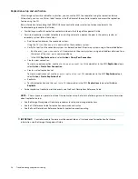
Page 98: ...port address obtained from the output of the show ports command above In the SMC Replications topic select Action Query Peer Connection Create a peer connection To create a peer connection use the cr...

Page 99: ...not running on each system used for replication Perform the following actions on each system used for virtual replication In the System topic select Action Update Firmware The Update Firmware panel o...

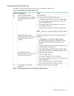
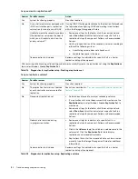
Page 100: ...ct Action Create Replication Set Table 24 Diagnostics for replication setup Creating a replication set Answer Possible reasons Action Yes System functioning properly No action required No The replicat...

Page 101: ...wering on the storage system components for the first time verify that the controller modules expansion modules and disk drives are using the current firmware release Periodically you should ensure th...

Page 102: ...s Model Description Form Model Description Form 5005 Fibre Channel 8 16Gb s SFP1 4 2U24 5005 Fibre Channel 8 16Gb s SFP1 4 2U12 5005 Internet SCSI 10GbE SFP2 4 2U24 5005 Internet SCSI 10GbE SFP2 4 2U1...

Page 103: ...AC unit chassis uses two PCMs of same model type 6 Expansion module for storage expansion I O used when chassis is configured as an EBOD a 3 port 12Gb s SBB expansion module 7 Controller module host...

Page 104: ...e as AC unit chassis uses two PCMs of same model type 6 Expansion module for storage expansion I O used when chassis is configured as an EBOD a 3 port 12Gb s SBB expansion module 7 Controller module h...

Page 105: ...sideplane baseplanes included with chassis not available separately 6 Power supply unit PSU available as AC module chassis uses two PSUs of same model type 7 Fan cooling module FCM chassis uses five...

Page 106: ...106 Troubleshooting and problem solving Figure 73 SBB IOMs used in 5005 4005 Series storage enclosures 4 port SAS controller module 4 port FC iSCSI controller module 3 port expansion module...

Page 107: ...ontainers Keep electrostatic sensitive parts in their containers until they arrive at static protected workstations Place parts in a static protected area before removing them from their containers Av...

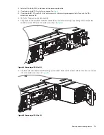
Page 108: ...pair See CAUTION bullets regarding electrostatic discharge and anti static protection on page 107 TIP The illustrations show PCM module replacement within the right slot as you view the enclosure rear...

Page 109: ...nclosure is powered off 6 Verify that the power cord is disconnected 7 Grasp the latch and the side of the PCM handle between thumb and fore finger squeeze together and open the handle to cam the PCM...

Page 110: ...at cooling fans are spinning with no fail states Verify that Ops panel states show no amber module faults 7 If replacing two PCMs repeat steps 1 through 5 being mindful of the illustrations TIP on pag...

Page 111: ...ive carrier module 1 Press the latch in the carrier handle towards the handle hinge to release the carrier handle as shown below Figure 76 Removing a LFF disk drive module 1 of 2 2 Gently move the dri...

Page 112: ...utside the enclosure See step 1 of the procedure described on page 113 1 Release the drive carrier handle by depressing the latch in the handle Figure 78 LFF drive carrier module in open position 2 In...

Page 113: ...ease refer to Figure 81 when using this procedure 1 Carefully put the T10 lock key into the cutout in the handle The LFF disk module is shown in the example below On SFF disk modules the socket is loc...

Page 114: ...ndle downward to release the carrier handle so that it can revolve outward as shown below Figure 82 Removing a SFF disk drive module 1 of 2 2 Gently move the drive carrier module outward from the driv...

Page 115: ...s and opening the hinged handle as shown in Figure 84 page 115 Insert the carrier into the enclosure in a vertical position IMPORTANT Make sure the carrier is positioned such that the disk is on its l...

Page 116: ...er modules must be fitted to all unused drive slots See also Figure 39 page 47 Replacing an IOM IMPORTANT The 5005 4005 Series storage enclosures support dual controller configuration only If a partne...

Page 117: ...escribed in these instructions 2 Wait 30 minutes this pause ensures that the controller and its ownership of disk groups has sufficient time to stabilize See also Verifying component operation page 12...

Page 118: ...or since the controller was restarted Record the numbers displayed 2 Run the show disk group statistics command a second time This provides you a specific window of time the interval between requesti...

Page 119: ...ot swap a single controller module in an operational enclosure provided you first shut down the faulty controller using the SMC or the CLI In a dual controller environment if replacing both controller...

Page 120: ...as shown in detail No 2 within Figure 88 NOTE The illustration above shows a 4 port controller module of model type SAS However the procedure applies to all IOMs discussed herein They all use the same...

Page 121: ...the IOM to its connector on the back of the midplane 5 Reconnect the cables NOTE In a dual controller system in which PFU is enabled when you update the firmware on one controller the system automati...

Page 122: ...work environment to accommodate chassis replacement Verifying component failure The controller enclosure CRU includes the enclosure s metal housing the module runner system the integrated Ops panel a...

Page 123: ...ssis to the rack and rails Table 33 Replacing a 2U storage enclosure chassis and installing its CRUs To accomplish this sequential process See the following procedures 1 Facing the front of the 2U enc...

Page 124: ...Using the applicable retaining screws secure the front and rear of the enclosure chassis to the rack and rails Completing the process This section provides a procedure for ensuring that the CRU compo...

Page 125: ...ed and provisioned the system and enabled event notification Select from the following methods to verify component operation Use the SMC to check the health icons values of the system and its componen...

Page 126: ...osure front panel See also Figure 18 page 29 Opening a drawer 1 Verify that the anti tamper locks are not engaged The red arrows on the locks point inwards if the locks are disengaged as shown in Figu...

Page 127: ...w drawer centric views of the enclosure and DDICs are properly aligned for insertion into the disk slots See CAUTION bullets regarding electrostatic discharge and anti static protection on page 107 Re...

Page 128: ...s listed in step 1 above 4 On the face of the DDIC push the latch button in the direction shown in Figure 92 page 128 to unlock the DDIC from its seated position in the slot Figure 92 Removing a DDIC...

Page 129: ...es may spread the 42 disks of an expansion package across those enclosures provided the DDICs are installed 14 at a time to completely fill empty rows The installation pattern providing the best airfl...

Page 130: ...row Top drawer back row Bottom drawer back row Replacing a PSU Illustrations in the power supply unit module replacement procedures show rear panel views of the enclosure and PSUs are properly aligned...

Page 131: ...a Push the release latch to the right and hold it in place detail No 1 b With your other hand grasp the handle and pull the PSU outward detail No 2 Supporting the PSU with both hands remove it from t...

Page 132: ...nd that the Ops panel states show no amber module faults 7 If replacing both PSUs repeat steps 1 through 6 Replacing an FCM Illustrations in the fan cooling module replacement procedures show rear pan...

Page 133: ...le may be defective Check the SMC and the event logs for more information Using the management interfaces the SMC or CLI determine if the health of the new FCM is OK Verify that the Module OK LED is g...

Page 134: ...the enclosure and IOMs are properly aligned for insertion into the IOM slots 1 Verify that you have successfully shut down the controller module using the SMC or the CLI 2 Locate the enclosure whose...

Page 135: ...common ground earth point NOTE When performing the following procedure refer to Figure 101 1 Examine the IOM for damage and closely inspect the interface connector Do not install if the pins are bent...

Page 136: ...ave received the replacement enclosure See CAUTION bullets regarding electrostatic discharge and anti static protection on page 107 1 Schedule down time that will allow for shutdown sixty minutes of r...

Page 137: ...ial process See the following procedures 1 Facing the front of the 5U enclosure access the drawers and remove DDICs from the damaged chassis Place them in a static protected work area nearby 1 a Openi...

Page 138: ...he failed chassis integrated ear components and covers are provided with the replacement chassis CRU 4 Maintaining a level position carefully slide the enclosure chassis from the rack 5 Place the chas...

Page 139: ...ing flange to rearmost enclosure extremity 602 9 mm 23 74 in Depth from face of Ops panel to rearmost enclosure extremity 629 6 mm 24 79 in Table 36 5U84 enclosure dimensions Specification Metric unit...

Page 140: ...12 192 meters 330 to 40 000 feet Shock operating 5 0 g 10 ms sine pulses Y axis Shock non operating 2U enclosures 30 0 g 10 ms sine pulses 5U enclosures 30 0 g 10 ms sine pulses Z axis 20 0 g 10 ms si...

Page 141: ...riable fan speed control Table 39 2U Power cooling module specifications continued Specification Measurement description Table 40 5U Power supply unit specifications Specification Measurement descript...

Page 142: ...nse Properly shielded and grounded cables and connectors must be used in order to meet FCC emission limits The supplier is not responsible for any radio or television interference caused by using othe...

Page 143: ...isposing of this equipment Radiated emissions limit levels CFR47 Part 15B Class A EN55022 Class A CISPR Class A Harmonics and flicker EN61000 3 2 3 Immunity limit levels EN55024 Table 42 EMC complianc...

Page 144: ...t a new device is connected or might not be able to communicate with it For Linux computers no new driver files are needed but a Linux configuration file must be created or modified See also Setting p...

Page 145: ...onnecting to 5005 4005 Series controller enclosures The 5005 4005 Series provides a device driver for use in the Windows environment The USB device driver and installation instructions are available v...

Page 146: ...mmunicate out of band between the host and controller module for setting network port IP addresses To create a new connection or open an existing connection HyperTerminal 1 From the Windows Control Pa...

Page 147: ...er A or B in 2U enclosures it will either install right side up or upside down 2 If the SFP has a plug remove it before installing the transceiver Retain the plug 3 Flip the actuator open sweep up or...

Page 148: ...ed and the link is up For FC SFPs see Figure 32 page 40 and refer to table entry No 1 For 10GbE iSCSI SFPs see Figure 32 page 40 and refer to table entry No 2 For 1Gb iSCSI SFPs see Figure 33 page 41...

Page 149: ...80W 27 PSU 2214W 31 D DHCP obtaining IP addresses 70 server 70 disk drawers 5U RBODs EBODs 32 populating 5U84 with DDICs 48 disk modules DDIC with 2 5 disk and adapter 48 DDIC with 3 5 disk 47 dual pa...

Page 150: ...escription 54 installation 2U 54 installation 5U 55 required tools 53 safety precautions 17 replication replicating volumes 74 S Safety precautions electrical safety 17 rack system safety 17 safe hand...

Reviews: