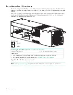
2U enclosure core product
25
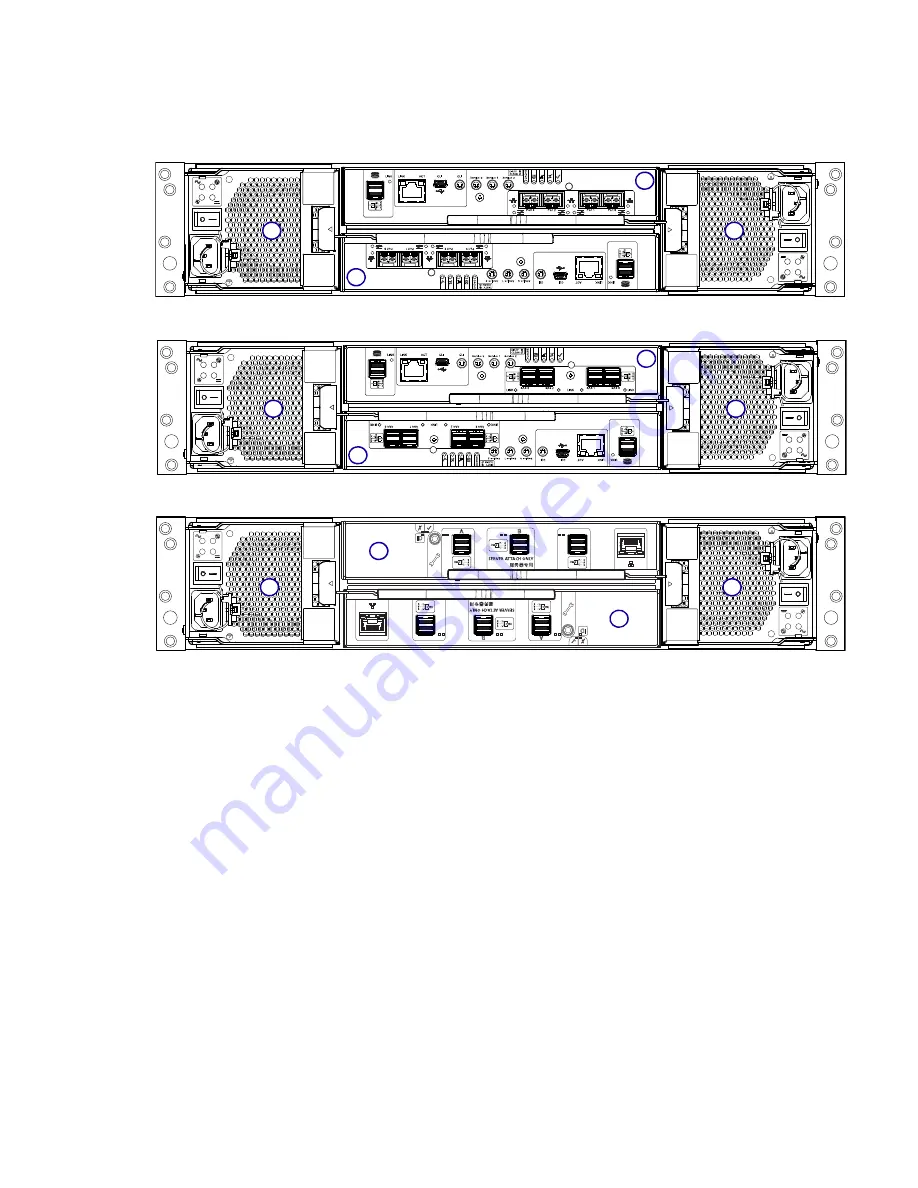
2U enclosure rear panel
Numeric designators on PCMs and alphabetic designators on IOMs indicate slot sequencing for modules used in 2U
enclosures. PCM and IOM modules are available as CRUs. The 5005 and 4005 RBODs use 4-port controller modules. The
5005/4005 Series RBODs support the J1212/J1224/J1284 EBODs for optionally adding storage.
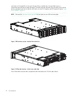
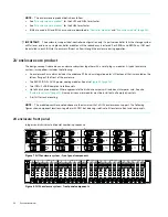
Figure 9 2U controller enclosure – rear panel components (4-port FC/iSCSI)
Figure 10 2U controller enclosure – rear panel components (4-port SAS)
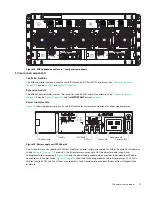
Figure 11 2U expansion enclosure – rear panel components
2U rear panel components
Controller modules
The top slot for holding IOMs is A and the bottom slot is B. The face plate details of the IOMs show the modules aligned
for use in A. In this orientation, the IOM latch appears at the bottom of the module. It is shown in closed/locked position.
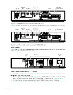
The diagrams below identify ports. See
“12Gb/s controller module LEDs” (page 39)
for LED identification. These
diagrams also show proper orientation for canister insertion into IOM slots located on the 5U84 enclosure rear panel.
shows CNC host interface ports that can be configured with 8/16Gb/s FC SFPs; 10GbE iSCSI SFPs; or 1Gb/s
RJ-45 SFPs. See
“Install an SFP transceiver” (page 147)
for installing qualified SFP options in CNC ports.
A
B
0
1
A
B
0
1
С
С
A
B
0
1


