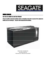
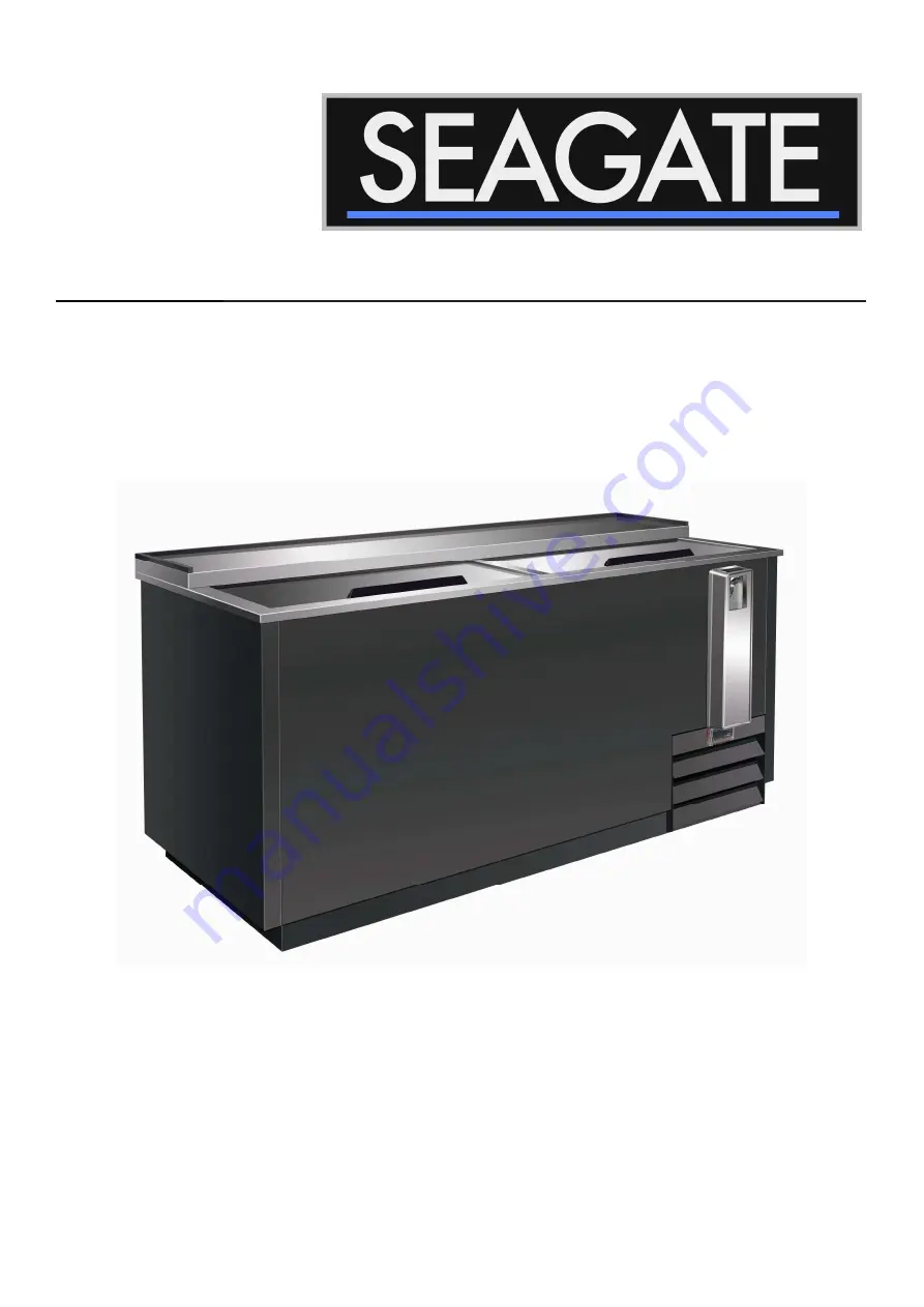
background image


BOTTLE COOLER

BOTTLE COOLER

BOTTLE COOLER

BOTTLE COOLER


Service, Installation and Care Manual 

Please read this manual completely before attempting to install or operate this equipment. 

Notify carrier of damage!    Inspect all components immediately. 


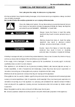
IMPORTANT INFORMATION 

READ BEFORE USE 

PLEASE SAVE THESE INSTRUCTIONS!


Summary of Contents for SBC-49

Page 1: ...Service Installation and Care Manual Please read this manual completely before attempting to install or operate this equipment Notify carrier of damage Inspect all components immediately IMPORTANT INF...

Page 2: ...chance of injury and let you know what can happen if the instructions are not followed If the supply cord is damaged it must be replaced by the manufacturer its service agent or similarly qualified pe...

Page 3: ...k L op ration le mouvement et l utilisation du r frig rant ou le cong lateur doivent viter les dommages du tuyau r frig rant ou le rique de la fuite Caution Risk of Fire or Explosion due to Flammable...

Page 4: ...310 5 15P SEAG SBC64 115 60 1 3 0 20 1 2 5400 3 17 353 5 15P SEAG SBC95 115 60 1 3 3 26 1 2 7600 3 53 439 5 15P CONGRATULATIONS ON YOUR NEW COOLER Note these instructions apply to all coolers Installa...

Page 5: ...be placed in sunlight or closed to a heat radiating surface If your cooler is fitted with a lock the key should be kept out of the reach of children If your new cooler is to replace an older one which...

Page 6: ...the compressor 2 The factory setting for the temperature range is 34 F to 38 F SOLID STATE THERMOSTAT DESCRIPTIONS 1 FRONT PANEL COMMANDS To display target set point in programming mode it selects a...

Page 7: ...FROST Hold the key for more than 2 seconds and the manual defrost will start 2 4 HOW TO LOCK THE KEYBOARD 1 Hold the and keys for more than 3s 2 The POF message will be displayed and the keyboard will...

Page 8: ...Service and Installation Manual 8 WIRING DIAGRAM MODEL SEAG SBC49 SEAG SBC64 MODEL SEAG SBC95...

Page 9: ...Service and Installation Manual 9 WIRING DIAGRAM MODEL SEAG SBC49 SEAG SBC64 POWER SUPPLY L N 1 2...

Page 10: ...Service and Installation Manual 10 WIRING DIAGRAM MODEL SEAG SBC95 L N 1 2...

Page 11: ...mber of the unit batch serial number of the unit and proof of purchase Service coverage is limited to units located in the United States and Canada only Limitation Exclusive Warranty This part and lab...

Page 12: ...Service and Installation Manual 11...

Reviews: