Savvio 15K SAS Product Manual, Rev. B
63
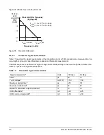
9.5.2.3
Receiver signal characteristics
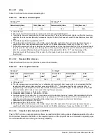
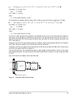
Table 18 defines the compliance point requirements of the signal at the receiver end of a TxRx connection as
measured into the test loads specified in figure 19 and figure 20.
a All tests in this table shall be performed with zero-length test load shown in figure 20.
b The skew measurement shall be made at the midpoint of the transition with a repeating 0101b pattern on the physical
link. The same stable trigger, coherent to the data stream, shall be used for both the Tx+ and Tx- signals. Skew is
defined as the time difference between the means of the midpoint crossing times of the Tx+ signal and the Tx- signal.
c The transmitter off voltage is the maximum A.C. voltage measured at compliance points when the transmitter is
unpowered or transmitting D.C. idle (e.g., during idle time of an OOB signal).
d Rise/fall times are measured from 20 % to 80 % of the transition with a repeating 0101b pattern on the physical link.
e The maximum difference between the V+ and V- A.C. RMS transmitter amplitudes measured on a CJTPAT test
pattern (see 9.5.2.3.3) into the test load shown in figure 20, as a percentage of the average of the V+ and V- A.C.
RMS amplitudes.
f The maximum difference in the average differential voltage (D.C. offset) component between the burst times and the
idle times of an OOB signal.
g The maximum difference in the average of the common mode voltage between the burst times and the idle times of
an OOB signal.
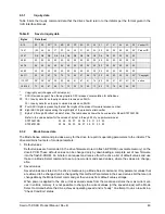
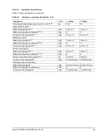
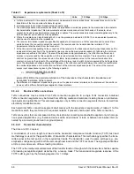
Table 18:
Receiver signal characteristics
Signal characteristic
Units
1.5 Gbps
3.0 Gbps
Jitter (see figure 16)
b
N/A
See table 19
See table 19
2 x Z2
mV(P-P)
1,200
1,600
2 x Z1
mV(P-P)
325
275
X1
a
UI
0.275
0.275
X2
UI
0.50
0.50
Skew
d
ps
80
75
Max voltage (non-op)
mV(P-P)
2.000
2.000
Minimum OOB ALIGN burst amplitude
c
mV(P-P)
240
240
Maximum noise during OOB idle time
c
mV(P-P)
120
120
Max near-end crosstalk
e
mV(P-P)
100
100
a The value for X1 shall be half the value given for total jitter in table 19. The test or analysis shall include the effects of
a single pole high-pass frequency-weighting function that progressively attenuates jitter at 20 dB/decade below a
frequency of ((bit rate) / 1,667).
b The value for X1 applies at a total jitter probability of 10
-12
. At this level of probability direct visual comparison
between the mask and actual signals is not a valid method for determining compliance with the jitter output
requirements.
c With a measurement bandwidth of 1.5 times the baud rate (i.e. 4.5 GHz for 3.0 Gbps).
d The skew measurement shall be made at the midpoint of the transition with a repeating 0101b pattern on the physical
link. The same stable trigger, coherent to the data stream, shall be used for both the Rx+ and Rx- signals. Skew is
defined as the time difference between the means of the midpoint crossing times of the Rx+ signal and the Rx- signal.
e Near-end crosstalk is the unwanted signal amplitude at receiver terminals DR, CR, and XR coupled from signals and
noise sources other than the desired signal. Refer to SFF-8410.
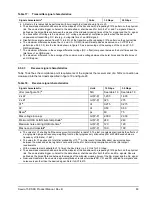
Table 17:
Transmitter signal characteristics
Signal characteristic
a
Units
1.5 Gbps
3.0 Gbps
Summary of Contents for ST600MP0074
Page 1: ...PRODUCT MANUAL Savvio 15K SAS 100407739 Rev B March 2007 ST973451SS ST936751SS ...
Page 4: ...ii Savvio 15K SAS Product Manual Rev B ...
Page 8: ......
Page 10: ...2 Savvio 15K SAS Product Manual Rev B ...
Page 14: ...6 Savvio 15K SAS Product Manual Rev B ...
Page 30: ...22 Savvio 15K SAS Product Manual Rev B ...
Page 34: ...26 Savvio 15K SAS Product Manual Rev B Figure 2 Typical ST936751SS current profile ...
Page 50: ...42 Savvio 15K SAS Product Manual Rev B ...
Page 78: ...70 Savvio 15K SAS Product Manual Rev B ...
Page 85: ......

