background image

“Graphics and specifications may change without notice”.

MS:169

ASSEMBLY MANUAL

Specifications:

Wing span ------------------------------66.9in (170cm).
Wing area -----------------764.2sq.in (49.3sq dm).
Weight ------------------------10.6lbs (4.8kg).
Length ------------------------------58.7in (149.0cm).
Engine  ------------------ 0.75-0.91cu.in ----2-stroke.
Engine  ------------------ 0.91-1.10cu.in ----4-stroke.
Radio -------------------4 channels with 6  servos.
Electric conversion: optional
Flying skill level  Advanced/Intermediate.

?

Summary of Contents for 169

Page 1: ...MANUAL Specifications Wingspan 66 9in 170cm Wingarea 764 2sq in 49 3sqdm Weight 10 6lbs 4 8kg Length 58 7in 149 0cm Engine 0 75 0 91cu in 2 stroke Engine 0 91 1 10cu in 4 stroke Radio 4channelswith6 servos Electricconversion optional Flyingskilllevel Advanced Intermediate ...

Page 2: ...n manual is designed to help you build a great flying aeroplane Please read this manual thoroughly before starting assembly of your GISPY MOTH Use the parts listing below to identify all parts WARNING Please be aware that this aeroplane is not a toy and if assembled or used incorrectly it is capable of causing injury to people or property WHEN YOU FLY THIS AEROPLANE YOU ASSUME ALL RISK RESPONSIBIL...

Page 3: ...in place per the steps that follow using a high quality thin C A glue 2 Remove each hinge from the wing panel and aileron and place a T pin in the center of each hinge Slide each hinge into the aileron until the T pin is snug against the aileron This will help ensure an equal amount of hinge is on either side of the hinge line when the aileron is mounted to the wing panel Note 1 Carefully remove t...

Page 4: ...ightly contact the wing during this procedure Ideally when the hinges are glued in place a 1 64 gap or less will be maintained throughout the lengh of the aileron to the wing panel hinge line The hinge is constructed of a special material that allows the C A to wick or penetrate and distribute throughout the hinge securely bonding it to the wood structure of the wing panel and aileron Note Hinge C...

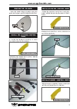
Page 5: ...iberglass control horn 2 Position the Control horn on the Aileron and use 30 minute Epoxy Elevator control horn Install the elevator control horn using the same method as same as the aileron control horns INSTALL ELEVATOR CONTROL HORN Fiberglass control horn Position the Control horn on the Aileron and use 30 minute Epoxy INSTALL RUDDER CONTROL HORN Repeat steps to install the rudder control horn ...

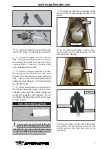
Page 6: ...fe cut one length of silicon fuel line Connect one end of the line to the weighted fuel pick up and the other end to the nylon pick up tube ENGINE MOUNT INSTALLATION Rudder control horn 1 Locate the items necessary to install the engine mount included with your model 2 Use four 4x30mm head bolts and four 4mm washers to attach the engine mount rails to the firewall Tighten the screws Make sure to u...

Page 7: ...bly into the tank It may be necessary to remove some of the flashing around the tank opening using a modeling knife If flashing is present make sure none falls into the tank You should mark which tube is the vent and which is the fuel pickup when you attach fuel tubing to the tubes in the stopper Once the tank is installed inside the fuselage it may be difficult to determine which is which FUEL TA...

Page 8: ...the lines to en sure the fuel lines have not become kinked inside the fuel tank compartment Air should flow through easily INSTALLING THE FUSELAGE SERVOS Throttle servo Elevator servo Rudder servo 1 Install the rubber grommets and brass collets onto the throttle servo Test fit the servo into the aileron servo mount 2 Secure the servos with the screws pro vided with your radio system Because the si...

Page 9: ...o the tube Position the engine between the mounts Use four M4x30mm machine screws to secure the engine to the mount as shown 5 Slide the pushrod tube in the firewall and guide it through the fuel tank mount Use medium C A to glue the tube to the firewall and the fuel tank mount 6 Connect the Z bend in the 450mm throttle pushrod to the outer hole of the carburetor arm Pushrod tube hole 9 Move the t...

Page 10: ...e items neccessary to install the wheel and wheel pants to the landing gear as shown WHEEL AND WHEEL PANTS INSTALLATION 2 Attach the Landing gear struts to the fuselage 3 Install the wheel M4x20mm A A B B M4x20mm M4x10mm C C D D D M3x10mm M3x10mm ...

Page 11: ...agullmodels com Trim and cut Trim and cut COWLING Trim and cut 1 Slide the fiberglass cowl over the engine and line up the back edge of the cowl with the marks you made on the fuselage then trim and cut as shown ...

Page 12: ...lease see pictures below Model size 75 91 size models Motor 50mm 310 rev per volt Propeller 15x8 16x8 ESC 80A Lipo Batteries 8 cell 4200mA Recommendation EP parts as shown not included with your model 2 While keeping the back edge of the cowl flush with the marks align the front of the cowl with the crankshaft of the engine The front of the cowl should be positioned so the crankshaft is in nearly ...

Page 13: ...llmodels com 4mm 3 Attach the motor to the front of the electric motor box using four 4mm blind nut four M3x15mm hex head bolts to secure the motor Please see picture shown M4x20mm Blind nut Epoxy 140mm M3x15mm 4mm ...

Page 14: ...Small weight Thread Battery Balsa stick Electric motor Epoxy Speed control 5 Attach the speed control to the side of the motor box using two sided tape and tie wraps Connect the appropriate leads from the speed control to the motor Make sure the leads will not interfere with the operation of the motor ...

Page 15: ...pin vise to drill the mouting holes in the blocks 4 Apply 2 3 drops of thin C A to each of the mounting holes Allow the C A to cure without using accelerator 6 Secure the servo to the aileron hatch using Phillips screwdriver and the screws provided with the servo 5 Use dental floss to secure the connection so they cannot become unplugged 7 Apply 1 2 drops of thin C A to each of the mounting tabs A...

Page 16: ...with four wood screws AILERON PUSHROD HORN INSTALLATION INSTALLING THE HORIZONTALSTABILIZER 1 Using a ruler and a pen locate the centerline of the horizontal stabilizer at the trail ing edge and place a mark Use a triangle and extend this mark from back to front across the top of the stabilizer Also extend this mark down the back of the trailing edge of the stabilizer ...

Page 17: ...r to the top and bottom of the stabilizer mounting area and to the stabilizer mounting platform sides in the fuselage Slide the stabilizer in place and realign Double check all of your mea surements once more before the epoxy cures Hold the stabilizer in place with T pins or mask ing tape and remove any excess epoxy using a paper towel and rubbing alcohol 4 With the stabilizer held firmly in place...

Page 18: ... INSTALLING VERITICAL FIN 1 Using a modeling knife remove the covering from over the precut hinge slot cut into the lower rear portion of the fuselage Remove covering Fill epoxy Fill epoxy 90º Vertical Stabilizer Horizontal Stabilizer Epoxy 3 Slide the vertical stabilizer back in place Using a triangle check to ensure that the vertical stabilizer is aligned 90º to the hori zontal stabilizer Hinge ...

Page 19: ... and to the lower hinge also Set the stabilizer in place and realign Double check all of your measure ments once more before the epoxy cures Hold the stabilizer in place with T pins or masking tape and remove any excess epoxy using a paper towel and rubbing alcohol Allow the ep oxy to fully cure before proceeding Rudder control horn Elevator control horn Elevator pushrod Rudder pushrod M2 lock nut...

Page 20: ... a pilot figure please use a sanding bar to sand the base of the figure so that it is flat INSTALLATION PILOT AND CANOPY 1 Locate items necessary to install pilot cockpit panel and canopy 2 A scale pilot is included with this ARF The Seagull Pilot included fitting well to the cockpit or you can order others scale pilot figures made by Seagull factory They are available at Seagull distributors 3x15...

Page 21: ...he box and aid in their location 4 Position the canopy onto the fuselage Trace around the canopy and onto the fuselage using a felt tipped pen APPLY THE DECALS 1 If all the decals are precut and ready to stick Please be certain the model is clean and free from oily fingerprints and dust Position decal on the model where desired using the photos on the box and aid in their location Epoxy M2x6mm Rec...

Page 22: ... 3 Install the dummy fuel tank ATTACHMENT WING FUSELAGE Wing tube Attach the aluminium tube into fuselage Insert two lower wing panels as pictures below M3x10mm M3x10mm M3x10mm Wing bolt Insert two upper wing panels as pictures below ...

Page 23: ...mm machine screw INSTALLATION WING STRUTS 1 Locate the items for this section of the manual Wing bolt 3 Repeat steps to prepare the remaining wing panel for installation and use pliers to bend four of the brass tabs at a slight angle Make the bend slightly biased toward the larger hole in the tab M3x20mm ...

Page 24: ... not There should be light tension on all the cables but not enough to change the position of the wing Once the cables have been tensioned begin by securing the crimps where the cables pass through the tabs near the fuselage Then secure the crimps at the cable ends Once tensioned use side cutters to trim the excess cable M3 clevis Crimp Metal Cable M3x20mm 1 Prepare one end of the cable by attachi...

Page 25: ...st add weight to the nose If the nose drops it is nose heavy and you must add weight to the tail to balance Accurately mark the balance point on the top of the wing on both sides of the fuselage The balance point is located 100 mm back from the leading edge of the wing at the wing root This is the balance point at which your model should balance for your first flights Later you may wish to experim...

Page 26: ...al 26 CONTROL THROWS Ailerons High Rate Up 25 mm Down 25 mm Low Rate Up 15 mm Down 15 mm Elevator High Rate Up 25 mm Down 25 mm Low Rate Up 15 mm Down 15 mm Rudder High Rate Right 40 mm Left 40 mm Low Rate Right 30 mm Left 30 mm ...

Page 27: ...oes not flip the servo re versing switch on your transmitter to change the direction E From behind the airplane look at the aileron on the right wing half Move the aileron stick to the right The right aileron should move up and the other aileron should move down If it does not flip the servo re versing switch on your transmitter to change the direction C Check the rudder Looking from behind the ai...

Reviews: