Focke- Wulf FW190
Instruction Manual.
14
.
INSTALLING THE FUSELAGE SERVOS
.
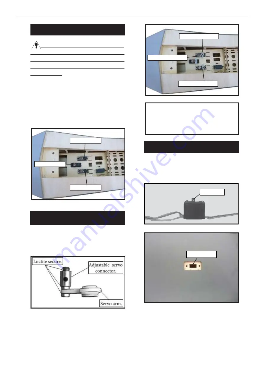
Because the size of servos difer, you
may need to adjust the size of the precut
opening in the mount. he notch in the
sides of the mount allow the servo lead to
pass through.
Install the rubber grommets and brass
collets into all servos. Test it the servos
into the fuselage servo mounts.
Secure the servos with the screws
provided with your radio system.
Elevator servo
1
.
Rudder servo
Elevator servo
THROTTLE SERVO ARM
INSTALLATION
Install adjustable servo connector in the
servo arm as same as picture below:
2
.
Elevator servo arm
Elevator servo arm
Minimum servo spec.
Torque
: 6.0V: 157.00 oz-in (11.31 kg-cm)
7.4V: 179.00 oz-in (12.89 kg-cm)
Rudder servo arm
1
.
INSTALLING THE RECEIVER SWITCH
Install the switch into the precut hole in
the side, in the fuselage.
3/32” Hole.
Trim and cut
1
.
2
.
Summary of Contents for FOCKE-WULF FW190
Page 10: ...Focke Wulf FW190 Instruction Manual 10 9 8 10 12 11 13 14 15 ...
Page 11: ...11 16 17 18 19 20 2 1 INSERT BOMB ONTO THE WING Epoxy 3 ...
Page 13: ...13 4 5 6 Epoxy Epoxy 7 WING ASSEMBLY 1 2 3 4 ...
Page 29: ...29 1 2 3 4 Steering arm Tail gear 7 5 6 8 9 ...
Page 35: ...35 15 20mm 12 15mm 20 25mm 20 25mm Wing Fuselage 12 15mm 15 20mm 30mm 80mm ...


