25
17
.
18.
19
.
15
.
16
.
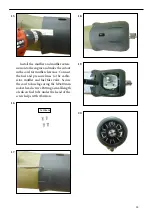
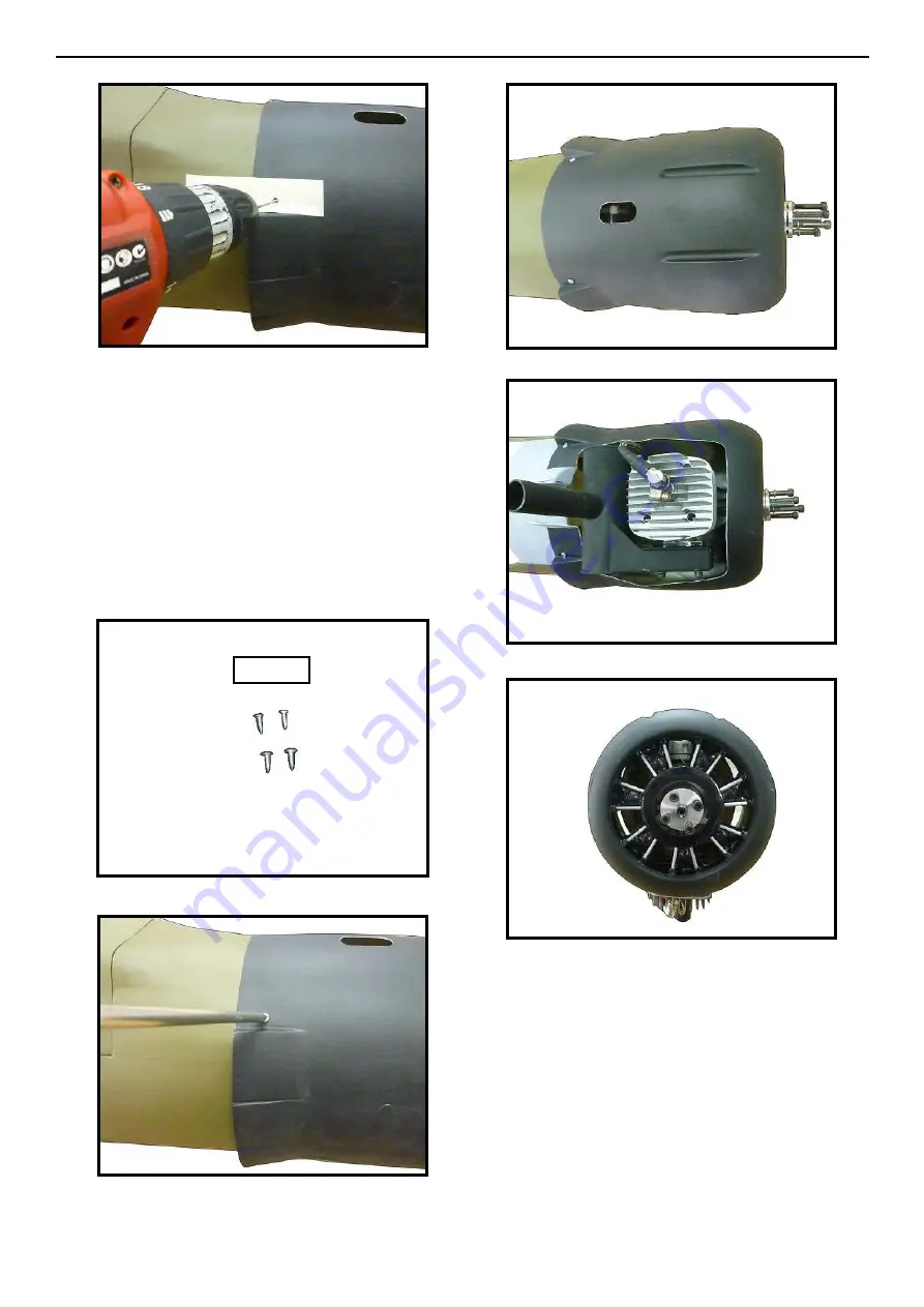
Install the muler and muler exten-
sion onto the engine and make the cutout
in the cowl for muler clearance. Connect
the fuel and pressure lines to the carbu-
retor, muler and fuel iler valve. Secure
the cowl to fuselage using the M3x10mm
socket head screws.Putting a small length
of silicon fuel tube under the head of the
screw helps with vibration.
3x10mm
20
.
Summary of Contents for SEA 334
Page 11: ...11 5 6 7 8 2 3 4 Epoxy 9 ...
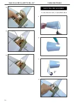
Page 14: ...Giant Zero A6M Gas ARF 50 60cc 86 Instruction Manual 14 28 25 29 26 30 27 31 3x10mm ...
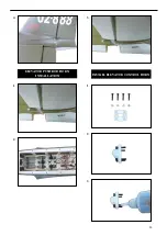
Page 15: ...15 1 1 2 3 4 2 WING ASSEMBLY ASEMBLE BOMB INTO THE WING 3 3x15mm ...
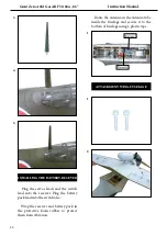
Page 21: ...21 22 19 23 21 25 20 24 Ignition Modude Pen 26 ...
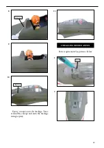
Page 23: ...23 COWLING Please see below pictures 1 4 5 6 7 2 3 3mm Epoxy ...
Page 30: ...Giant Zero A6M Gas ARF 50 60cc 86 Instruction Manual 30 2 6 3 7 4 8 5 9 Epoxy ...
Page 31: ...31 10 11 1 INSTALL RUDDER CONTROL HORN Epoxy 2 3 6 4 5 Epoxy Epoxy ...
Page 33: ...33 8 10 9 11 Epoxy 2 1 12 3 INSTALL ELEVATOR CONTROL HORN Epoxy ...
Page 35: ...35 4 1 2 ELEVATOR PUSHROD HORN INSTALLATION 3 1 2 3 INSTALL ELEVATOR CONTROL HORN ...
Page 41: ...41 3 4 5 6 Wing bolt 7 8 9 10 hen install wing guns on the wings ...


