background image

TAYLOR CRAFT 25E

Instruction Manual.

18

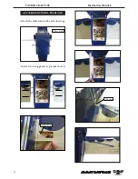
Wing bolt.

3x6mm

ATTACHMENT WING- FUSELAGE.

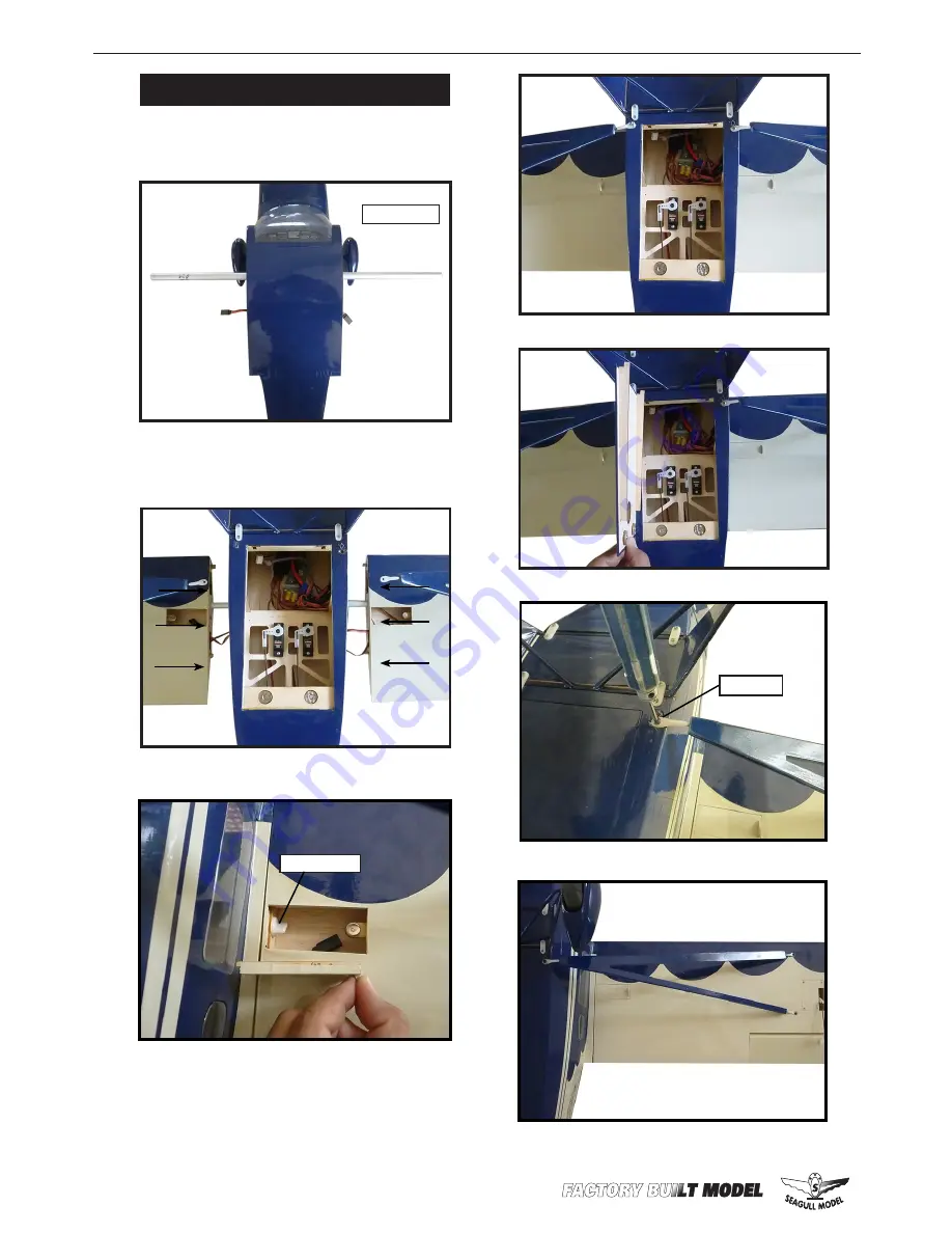
Attach the aluminium tube into fuselage.

 Insert two wing panels as pictures below.

Wing tube.

Summary of Contents for BC-12D

Page 1: ...in 157 5 cm Wing area 620 sq in 40 0 sq dm Weight 3 3 3 9 lbs 1 5 1 8 kg Length 40 9 in 103 8cm Motor 25 32 brushless motor Radio 4 channels with 4 servos Electric conversion Optional MS 193 Graphics and specifications may change without notice ARF A S S E M B L Y M A N U A L ...

Page 2: ...designed to help you build a great flying earoplane Please read this manual throughly before starting assembly of your User the parts listing below to indentify all parts INTRODUCTION WARNING KIT CONTENTS 1 2 3 3 6 7 4 5 2 Please be awere that this aeroplane is not a toy and if assemble or used incorrectly it is capable of causing injury to people or property WHEN YOU FLY THIS AEROPLANE YOU ASSUME...

Page 3: ... not glued in place It is imperative that you prop erly adhere the hinges in place per the steps that follow using a high quality thin C A glue 1 Carefully remove the aileron from one of the wing panels Note the position of the hinges 2 Remove each hinge from the wing panel and aileron and place a T pin in the center of each hinge Slide each hinge into the aileron until the T pin is snug against t...

Page 4: ...lect the aileron in the opposite direction from the opposite side Apply thin C A glue to each hinge making sure that the C A penetrates into both the aileron and wing panel 6 Using C A remover debonder and a pa per towel remove any excess C A glue that may have accumulated on the wing or in the aileron hinge area 7 Repeat this process with the other wing panel securely hinging the aileron in place...

Page 5: ...nto the eleva tor until the T pi n is snug against the elevator This will help ensure an equal amount of hinge is on either side of the hinge line when the elevator is mount ed to the horizontal stabilizer panel Glue the hinge hinges in place using the sametechniquesusedtohingtheailerons Epoxy HINGING THE RUDDER Glue the rudder hinges in place using the same techniques used to hinge the ai lerons ...

Page 6: ...hod as same as the aileron control horns INSTALL ELEVATOR CONTROL HORN Elevator control horn Epoxy Elevator Epoxy Epoxy Rudder control horn INSTALL RUDDER CONTROL HORN Repeat steps to install the rudder control horn as same as steps done for ailerons Rudder control horn Back Front Left Right ...

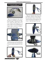
Page 7: ...crews and land ing gear straps to secure the landing gear to the bottom of the fuselage 3x10mm Fit the wheel pant on the axle Slide the wheel collar onthe axle and temporarily secure the collar flush with the end of the axle Slide the wheel pant and wheel onthe landing gear With both wheels and pants place rest the fuselage on the flat surface Check that there is clearance between the surface and ...

Page 8: ...ELAGE SERVOS Because the size of servos differ you may need to adjust the size of the precut opening in the mount The notch in the sides of the mount allow the servo lead to pass through 1 Install the rubber grommets and brass collets onto the fuselage servo Test fit the servo into the aileron servo mount 2 Secure the servos with the screws pro vided with your radio system Rudder Elevator 3x10mm 1...

Page 9: ...nterfere with the operation of the motor Speed control COWLING 1 Slide the fiberglass cowl over the en gine and line up the back edge of the cowl with the marks you made on the fuselage then trim and cut as shown 2 While keeping the back edge of the cowl flush with the marks align the front of the cowl with the crankshaft of the engine The front of the cowl should be positioned so the crankshaft i...

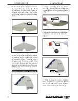
Page 10: ...the spinner cone If it does use a sharp modeling knife and carefully trim away the spinner cone where the propel ler comes in contact with it INSTALLING THE AILERON SERVOS Servos Small weight Thread Because the size of servos differ you may need to adjust the size of the precut opening in the mount The notch in the sides of the mount allow the servo lead to pass through 1 Using a small weight Weig...

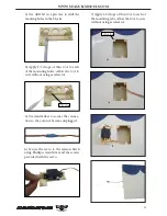
Page 11: ... Allow the C A to cure without using accelerator C A glue 5 Use dental floss to secure the connec tion so they cannot become unplugged 6 Secure the servo to the aileron hatch using Phillips screwdriver and the screws provided with the servo 7 Apply 1 2 drops of thin C A to each of the mounting tabs Allow the C A to cure without using accelerator C A glue ...

Page 12: ...N Please see below pictures Use a felt tip pen to mark the wire where it crosses the hole Use a pair of pliers to put a shrp 90 degree bend in the wire at the mark Bend at the mark 8mm M2 lock nut Metal clevis Snap keeper Snap keeper Servo arm Fuel tubing Hex Nut Mark Nylon Snap keeper ...

Page 13: ...er where it and the fuselage sides meet Do this on both the right and left sides and top and bottom of the stabilizer 5 Remove the stabilizer Using the lines you just drew as a guide carefully remove the covering from between them using a modeling knife Pen When cutting through the covering to re move it cut with only enough pressure to only cut through the covering itself Cutting into the balsa s...

Page 14: ... more epoxy to fill in any gaps that may exist that were not filled previously and clean up the excess using a paper towel and rubbing alcohol Epoxy INSTALLING VERTICAL STABILIZER 1 Using a modeling knife remove the covering from over the precut hinge slot cut into the lower rear portion of the fu selage Fill Epoxy 2 Mount the tailwheel assembly in place on the lower rear end of the vertical sta b...

Page 15: ...e Epoxy Ap ply a thin layer to the mounting slot and to bottom of the vertical stabilizer mounting area Apply epoxy to the bot tom and top edges of the filler block and to the lower hinge also Set the stabilizer in place and realign Double check all of your measurements once more before the epoxy cures Hold the stabilizer in place with T pins or masking tape and remove any excess epoxy using a pap...

Page 16: ...ecals are not precut please use scissors or a sharp hobby knife to cut the decals from the sheet Please be cer tain the model is clean and free from oily fingerprints and dust Position decal on the model where desired using the pho tos on the box and aid in their location 1 If all the decals are precut and ready to stick Please be certain the model is clean and free from oily fingerprints and dust...

Page 17: ...ULLMODELS COM 17 2 Wrap the receiver and battery pack in the protective foam rubber to protect them from vibration Receiver Battery INSTALLATION WING STRUTS Please see below pictures 3x6mm 3x6mm Battery 3x10mm ...

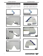
Page 18: ...TAYLOR CRAFT 25E Instruction Manual 18 Wing bolt 3x6mm ATTACHMENT WING FUSELAGE Attach the aluminium tube into fuselage Insert two wing panels as pictures below Wing tube ...

Page 19: ... difficult to slow down for landing Moving the balance aft makes the model more agile with a light er and snappier feel In any case please start at the location we recommend With the wing attached to the fuselage all parts of the model installed ready to fly and empty fuel tanks hold the mod el at the marked balance point with the stabilizer level 2 Mount the wing to the fuselage Using a couple of...

Page 20: ...TAYLOR CRAFT 25E Instruction Manual 20 ...

Page 21: ...e look at the aileron on the right wing half Move the aileron stick to the right The right aileron should move up and the other aileron should move down If it does not flip the servo reversing switch on your transmitter to change the direction 1 Completely charge your trans mitter and receiver batteries before your first day of flying 2 Check every bolt and every glue joint in the to ensure that e...

Reviews: