5
© Sealevel Systems, Inc. 3541 Manual | SL9150 12/2022
Card Setup
The
C4-104.ULTRA
contains two DIP-Switches and a jumper strap for each port, which must be set for
proper operation.
Address Selection
Each port on the
C4-104.ULTRA
occupies sixteen consecutive I/O locations. A DIP-switch is used to set
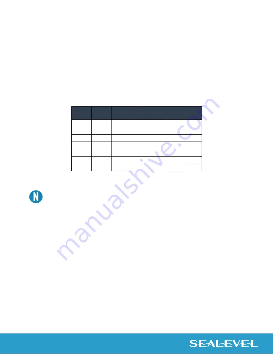
the base address for these locations. The following table shows the addressing options available. If
different address options are required, please contact Sealevel Systems Technical Support about a custom
PAL option.
SW1-1 SW1-2 SW1-3
Port
1
Port
2
Port
3
Port 4
OFF
OFF
ON
300
310
320
330
OFF
ON
OFF
400
410
420
430
OFF
ON
ON
500
510
520
530
ON
OFF
OFF
600
610
620
630
ON
OFF
ON
1500 1510 1520 1530
ON
ON
OFF
3220 3230 3240 3250
ON
ON
ON
4220 4230 4240 4250
Figure 1 - Address Selection Table
Refer to Appendix A for common address contentions.
Port Enable / Disable
All four ports on the can be enabled or disabled by setting the three switches in the ‘Off’ position. The port
is enabled when a valid I/O selection is made. If the adapter is disabled, be sure to disable the interrupt
request by removing the IRQ jumper.
Interrupt Modes
DIP-Switch positions ‘S’ and ‘M’ on switch SW1 selects the interrupt mode for the adapter.
With the ‘
S
’ selected, the adapter is in a (
S
)hared interrupt mode, which allows more than one adapter to
access a single IRQ. Any two or more PC-104 adapters can share a common IRQ by placing the jumpers on
the same IRQ setting and setting the appropriate selections for interrupt mode.
‘
M
’ indicates the inclusion of a 1K-ohm pull-down resistor required on one adapter when sharing interrupts.


