background image


18 

© Sealevel Systems, Inc.  7402 Manual   |   SL9063  7/2021 

Why use an ISP? 

The answer to the polling inefficiency was the Interrupt Status Port


(ISP). The ISP


is a read only 8-bit register 

that sets a corresponding bit when an interrupt is pending. Port 1 interrupt line corresponds with Bit D0 of 
the status port, Port 2 with D1 etc. The use of this port means that the software designer now only has to 
poll a single port to determine if an interrupt is pending. 

The ISP is at Base+7 on each 

port (Example: Base = 280 Hex, Status Port = 287, 28F… etc.). The ULTRA 

COMM+422.PCI will allow any one of the available locations to be read to obtain the value in the status 
register. Both status ports on the ULTRA COMM+422.PCI are identical, so any one can be read. 

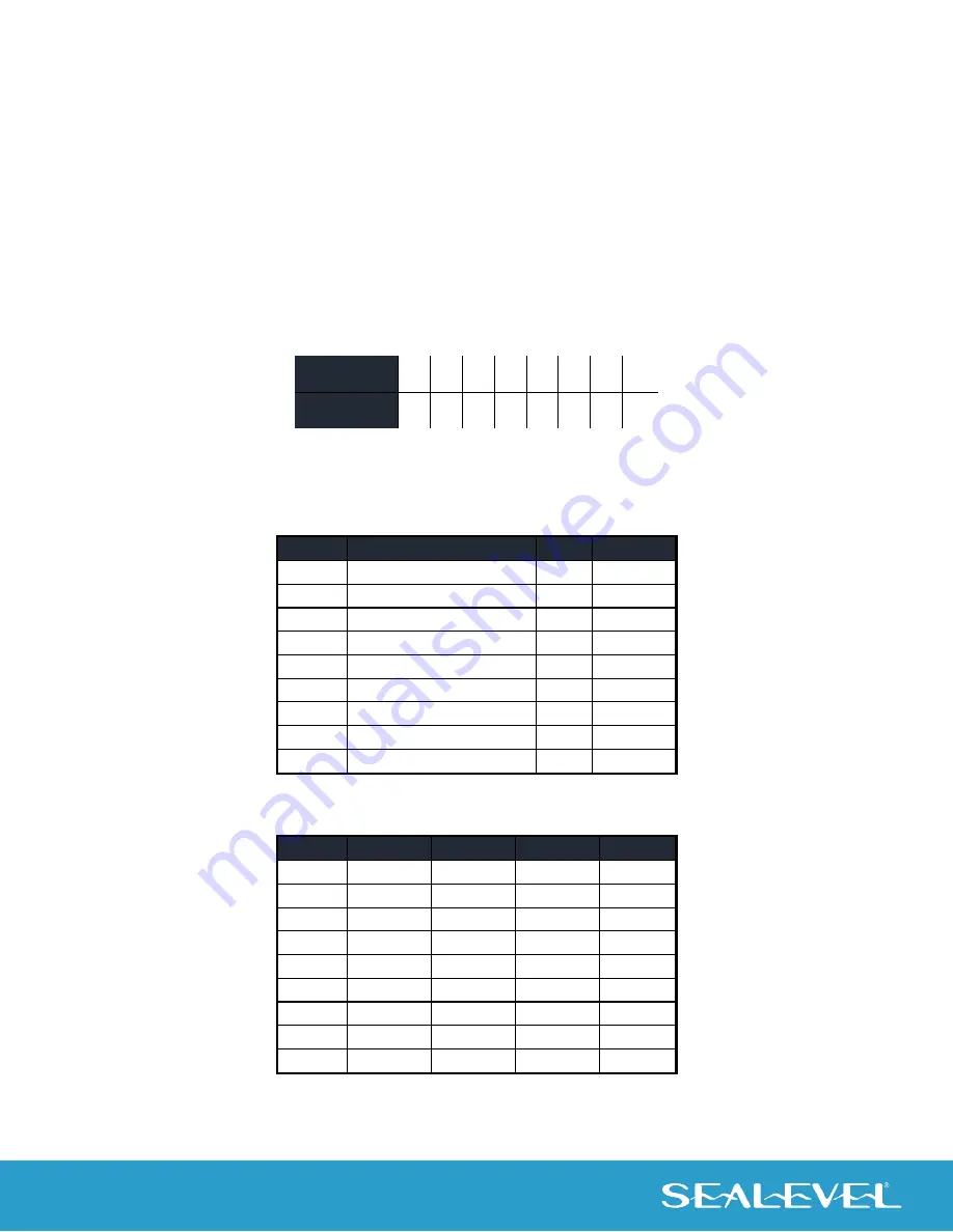
Example: This indicates that Channel 2 has an interrupt pending. 

Bit Position: 

Value Read: 

Connector Pin Assignments 

RS-422/485 (DB-9 Male)


Signal 

Name 

Pin # 

Mode 

GND 

Ground 


TX + 

Transmit Data Positive 

Output 

TX- 

Transmit Data Negative 

Output 

RTS+ 

Request To Send Positive 

Output 

RTS- 

Request To Send Negative 

Output 

RX+ 

Receive Data Positive 

Input 

RX- 

Receive Data Negative 

Input 

CTS+ 

Clear To Send Positive 

Input 

CTS- 

Clear To Send Negative 

Input 

DB-37 Connector Pin Assignments


Port # 

GND 

33 

14 

24 

TX- 

35 

12 

26 

RTS- 

17 

30 

21 

TX+ 

34 

13 

25 

RX- 

36 

11 

27 

CTS- 

16 

31 

22 

RTS+ 

18 

29 

20 

RX+ 

37 

10 

28 

CTS+ 

15 

32 

23 

Summary of Contents for 7402

Page 1: ...1 Sealevel Systems Inc 7402 Manual SL9063 7 2021 ULTRA COMM 422 PCI User Manual 7402 ...

Page 2: ...FORE YOU GET STARTED 5 CARD SETUP 9 INSTALLATION 15 TECHNICAL DESCRIPTION 17 PRODUCT OVERVIEW 19 APPENDIX A TROUBLESHOOTING 20 APPENDIX B ELECTRICAL INTERFACE 21 APPENDIX C ASYNCHRONOUS COMMUNICATIONS 22 APPENDIX D CAD DRAWING 23 APPENDIX E HOW TO GET ASSISTANCE 24 APPENDIX F COMPLIANCE NOTICES 25 WARRANTY 26 ...

Page 3: ...g or on anti static mats Grounding Methods The following measures help to avoid electrostatic damages to the device Cover workstations with approved antistatic material Always wear a wrist strap connected to workplace as well as properly grounded tools and equipment Use antistatic mats heel straps or air ionizers for more protection Always handle electrostatically sensitive components by their edg...

Page 4: ...S 485 and RS 422 modes the card works seamlessly with the standard operating system serial driver In RS 485 mode our special auto enable feature allows the RS 485 ports to be viewed by the operating system as a COM port This allows the standard COM driver to be utilized for RS 485 communications Our on board hardware automatically handles the RS 485 driver enable Features Compliant with RoHS and W...

Page 5: ...B 9 connectors Advisory Conventions Warning The highest level of importance used to stress a condition where damage could result to the product or the user could suffer serious injury Important The middle level of importance used to highlight information that might not seem obvious or a situation that could cause the product to fail Note The lowest level of importance used to provide background in...

Page 6: ...176 DB9 Female RS 422 to DB25 Male RS 530 Cable 10 inch Length Convert any Sealevel RS 422 DB9 Male Async Adapter to an RS 530 DB25 Male pinout Useful in situations where RS 530 cabling exists and a multiport Sealevel RS 422 adapter is to be used Terminal Blocks Terminal Block Dual DB9 Female to 18 Screw Terminals Item TB06 The TB06 terminal block includes dual right angle DB 9 female connectors t...

Page 7: ...for RS 422 and RS 485 networks yet it will work with any DB9 serial connection including RS 232 The TB05 includes holes for board or panel mounting The TB05 is designed to connect directly to Sealevel DB9 serial cards or any cable with a DB9M connector DB9 Female RS 422 to DB9 Female Opto 22 Optomux Converter Item DB103 The DB103 is designed to convert a Sealevel DB9 male RS 422 connector to a DB9...

Page 8: ... as follows Port Clock DIV Mode Enable Mode Port 1 4 Auto Port 2 4 Auto Port 3 4 Auto Port 4 4 Auto To install the ULTRA COMM 422 PCI using factory default settings refer to Installation on page 9 For your reference record installed ULTRA COMM 422 PCI settings below Port Clock DIV Mode Enable Mode Port 1 Port 2 Port 3 Port 4 ...

Page 9: ...that the user can effectively use the ULTRA COMM 422 PCI in an RS 485 application with existing i e standard RS 232 software drivers Headers J1B J4B are used to control the RS 485 mode functions for the driver circuit The selections are RTS enable silk screen RT or Auto enable silk screen AT The Auto enable feature automatically enables disables the RS 485 interface The RTS mode uses the RTS modem...

Page 10: ... Headers J1B J4B RS 422 Figure 2 Headers J1B J4B RS 485 Auto Enabled with No Echo Figure 3 Headers J1B J4B RS 485 Auto Enabled with Echo Figure 4 Headers J1B J4B RS 485 RTS Enabled with No Echo Figure 5 Headers J1B J4B RS 485 RTS Enabled with Echo AT RT NE AT RT NE AT RT NE AT RT NE AT RT NE ...

Page 11: ...s Headers J1A J4A allow the user to customize this interface to their specific requirements Each jumper position corresponds to a specific portion of the interface If multiple ULTRA COMM 422 PCI adapters are configured in an RS 485 network only the boards on each end should have jumpers T P P ON Refer to the following table for each position s operation Name Function P Adds or removes the 1K ohm p...

Page 12: ... modes are selected at Headers J1C through J4C To select the Baud rates commonly associated with COM ports i e 2400 4800 9600 19 2 115 2K Bps place the jumper in the divide by 4 mode silk screen DIV4 Figure 7 Clocking Mode Divide By 4 To double these rates up to a maximum rate for 230 4K bps place the jumper in the divide by 2 silk screen DIV2 position Figure 8 Clocking Mode Divide By 2 DIV1 DIV2 ...

Page 13: ... 1200 bps 300 bps 2400 bps 600 bps 4800 bps 1200 bps 9600 bps 2400 bps 19 2K bps 4800 bps 57 6 K bps 14 4K bps 115 2 K bps 28 8K bps 230 4K bps 57 6 K bps 460 8K bps 115 2 K bps If your communications package allows the use of Baud rate divisors choose the appropriate divisor from the following table For this Data Rate Choose this Divisor 1200 bps 384 2400 bps 192 4800 bps 96 9600 bps 48 19 2K bps...

Page 14: ...ta Rate 1200 bps 600 bps 2400 bps 1200 bps 4800 bps 2400bps 9600 bps 4800 bps 19 2K bps 9600 bps 38 4K bps 19 2K bps 57 6 K bps 28 8K bps 115 2 K bps 57 6 K bps 230 4 K bps 115 2 K bps If your communications package allows the use of Baud rate divisors choose the appropriate divisor from the following table For this Data Rate Choose this Divisor 1200 bps 192 2400 bps 96 4800 bps 48 9600 bps 24 19 ...

Page 15: ...Select Download Now for SeaCOM for Windows 4 The setup files will automatically detect the operating environment and install the proper components Follow the information presented on the screens that follow 5 A screen may appear with text similar to The publisher cannot be determined due to the problems below Authenticode signature not found Please click the Yes button and proceed with the install...

Page 16: ... of files both explains typical Linux serial implementations and informs the user about Linux syntax and preferred practices User can use a program such as 7 Zip to extract the tar gz file In addition the software selectable interface settings can be accessed by referencing seacom utilities 7402mode For additional software support including QNX please call Sealevel Systems Technical Support 864 84...

Page 17: ... is the same process the PC uses to alert the CPU that a task must be performed The CPU upon receiving an interrupt makes a record of what the processor was doing at the time and stores this information on the stack this allows the processor to resume its predefined duties after the interrupt is handled exactly where it left off Every main sub system in the PC has its own interrupt frequently call...

Page 18: ...ns to be read to obtain the value in the status register Both status ports on the ULTRA COMM 422 PCI are identical so any one can be read Example This indicates that Channel 2 has an interrupt pending Bit Position 7 6 5 4 3 2 1 0 Value Read 0 0 0 0 0 0 1 0 Connector Pin Assignments RS 422 485 DB 9 Male Signal Name Pin Mode GND Ground 5 TX Transmit Data Positive 4 Output TX Transmit Data Negative 3...

Page 19: ...g All Sealevel Systems Printed Circuit boards are built to UL 94V0 rating and are 100 electrically tested These printed circuit boards are solder mask over bare copper or solder mask over tin nickel Power Consumption Supply line 5 VDC Rating 620 mA Mean Time Between Failures MTBF Greater than 150 000 hours Calculated Physical Dimensions Board length 5 0 inches 12 7 cm Board height including Goldfi...

Page 20: ...hoosing an I O address and IRQ 4 Make sure the Sealevel Systems adapter is securely installed in a motherboard slot 5 If you are utilizing an operating system prior to Windows 7 please contact Sealevel by calling 864 843 4343 or emailing support sealevel com to receive more information in regard to the utility software which will determine if your product is functioning properly 6 Only users runni...

Page 21: ...tor RS 485 RS 485 is backwardly compatible with RS 422 however it is optimized for party line or multi drop applications The output of the RS 422 485 driver is capable of being Active enabled or Tri State disabled This capability allows multiple ports to be connected in a multi drop bus and selectively polled RS 485 allows cable lengths up to 4000 feet and data rates up to 10 Megabits per second T...

Page 22: ...d of the character is defined by the transmission of a pre defined number of stop bits usually 1 1 5 or 2 An extra bit used for error detection is often appended before the stop bits Figure 9 Asynchronous Communications This special bit is called the parity bit Parity is a simple method of determining if a data bit has been lost or corrupted during transmission There are several methods for implem...

Page 23: ...23 Sealevel Systems Inc 7402 Manual SL9063 7 2021 Appendix D CAD Drawing 4 2 5 2 ...

Page 24: ...to this to answer many common questions This section can be found at http www sealevel com faq htm 4 Sealevel Systems maintains a Home page on the Internet Our home page address is https www sealevel com The latest software updates and newest manuals are available via our FTP site that can be accessed from our home page Technical support is available Monday to Friday from 8 00 A M to 5 00 P M East...

Page 25: ...d to correct the interference at the users expense EMC Directive Statement Products bearing the CE Label fulfill the requirements of the EMC directive 89 336 EEC and of the low voltage directive 73 23 EEC issued by the European Commission To obey these directives the following European standards must be met EN55022 Class A Limits and methods of measurement of radio interference characteristics of ...

Page 26: ...nty Warranty service may be obtained by delivering the Product to Sealevel and providing proof of purchase Customer agrees to ensure the Product or assume the risk of loss or damage in transit to prepay shipping charges to Sealevel and to use the original shipping container or equivalent Warranty is valid only for original purchaser and is not transferable This warranty applies to Sealevel manufac...

Reviews: