background image


13 

© Sealevel Systems, Inc.  1102 Manual   |  SL9135  6/2021 


On power-up, the IC485+ scans the Mode Select DIP-switch (SW1) one time to determine the 
communication mode and then branches to the selected control logic. No attempt is made to 
periodically check the switch for a mode change. This is done for two reasons. First, our 
experience shows that a device such as this is configured for the required application and the 
mode is not changed after this.  Due to this reason, the product is not burdened with the overhead 
of always checking this switch. At higher baud rates this becomes especially critical due to the 
speed of the onboard microcontroller. The utmost priority is given to sampling the incoming 
data.  To install Sealevel software, you must log in as an administrator or have  
administrator privileges. 

If  the IC485+ has  been  configured  for  a  particular  mode,  and  for  some  reason  it  has  become 
necessary to change the communication mode, remove power, reconfigure the Mode Select DIP-
switch (SW1) for the new mode, and reapply power.   


Summary of Contents for IC485+

Page 1: ...1 Sealevel Systems Inc 1102 Manual SL9135 6 2021 IC485 User Manual 1102 ...

Page 2: ...ATING SYSTEM INSTALLATION FOR WINDOWS USERS 10 TECHNICAL DESCRIPTION 14 TECHNICAL SPECIFICATIONS 16 APPENDIX A TROUBLESHOOTING 17 APPENDIX B HOW TO GET ASSISTANCE 18 APPENDIX C ELECTRICAL INTERFACE 19 APPENDIX D ASYNCHRONOUS COMMUNICATIONS 20 APPENDIX E SILK SCREEN 21 APPENDIX F COMPLIANCE NOTICES 22 WARRANTY 23 ...

Page 3: ...ntial Select RS 485 and capture data from multiple peripherals in an RS485 multi drop network Up to 31 RS 485 devices can be connected to automate your data collection In RS 422 and RS 485 Auto modes the card works seamlessly with the standard operating system serial driver Two additional methods are provided to control the communication line in RS 485 mode The Data Enable mode uses the transmitte...

Page 4: ...ventions Warning The highest level of importance used to stress a condition where damage could result to the product or the user could suffer serious injury Important The middle level of importance used to highlight information that might not seem obvious or a situation that could cause the product to fail Note The lowest level of importance used to provide background information additional tips o...

Page 5: ...ttings The IC485 factory default settings are as follows Port Electrical Specification Port 1 RS 422 To install the IC485 using factory default settings refer to Installation For your reference record installed IC485 settings below Port Electrical Specification Port 1 ...

Page 6: ...rd MicroChip PIC microcontroller to sense the baud rate and control the transmitter enable signal based on the detected baud rate The logic assumes a minimum baud rate of 1200bps and a word length of 10 bits 1 start bit 8 data bits and 1 stop bit For baud rates of 38 4K or less line turnaround should not exceed 4 bit times 57 6K should not exceed 10 bit times and 115 2K should not exceed 20 bit ti...

Page 7: ...102 Manual SL9135 6 2021 Communication Mode Examples Dip switch SW1 Figure 1 Dip switch SW1 RS 422 Figure 2 Dip switch SW1 RS 485 Auto Enable Figure 3 Dip switch SW1 RS 485 RTS Enable Figure 4 Dip switch SW1 RS 485 Data Enable ...

Page 8: ...on 6 is used to control the RS 485 enable disable functions for the receiver circuit and determines the state of the RS 422 485 driver The RS 485 Echo is the result of connecting the receiver inputs to the transmitter outputs Every time a character is transmitted it is also received This can be beneficial if the software can handle echoing i e using received characters to throttle the transmitter ...

Page 9: ...ual SL9135 6 2021 Electrical Interface Examples DIP switch SW2 Figure 6 RS 422 with Termination and Receiver Echo Figure 7 RS 485 2 wire with Termination and Receiver No Echo Figure 8 RS 485 2 wire no Termination and Receiver No Echo ...

Page 10: ...e driver database Choose Asynchronous COM Port Software SeaCOM Continue with the installation until the Setup Type dialog as shown below appears Choose WinSSD Utility to install just the diagnostic tool A Start Menu Program Group SeaCOM will be created and WinSSD can be started from there RS 485 Two Wire and RS 485 Four Wire Slave Installation If your application is 2 wire Half Duplex RS 485 or 4 ...

Page 11: ...o pull the line to the proper state Due to this termination must not be used and thus data rate and cable length are reduced accordingly The choice of which method to use is simple If your data stream permits the use of the Auto Enable mode always use this option as it permits the simplest installation If Auto Enable is not an option and you are using the IC485 in a Windows based system setup the ...

Page 12: ...ons this is adequate The Auto Enable and Data Enable modes can also be used Refer to your operating system documentation for specifics Physical Installation The IC485 can be connected to any existing RS 232 port A cable such as Sealevel s CA 177 can be used to attach the IC485 DB 25F to the PC s DB 9M connector 1 Locate an existing RS 232 COM port and connect the IC485 2 With the IC485 case open c...

Page 13: ...mode is not changed after this Due to this reason the product is not burdened with the overhead of always checking this switch At higher baud rates this becomes especially critical due to the speed of the onboard microcontroller The utmost priority is given to sampling the incoming data To install Sealevel software you must log in as an administrator or have administrator privileges If the IC485 h...

Page 14: ...gnals DB 25 Female Signal Name Pin Mode GND Ground 7 RD Receive Data 3 Input CTS Clear To Send 5 Input DSR Data Set Ready 6 Input DCD Data Carrier Detect 8 Input RI Ring Indicator 22 Input TD Transmit Data 2 Output RTS Request To Send 4 Output DTR Data Terminal Ready 20 Output These assignments meet EIA TIA ANSI 232E DTE The modem control signals are biased in the following fashion RTS and CTS are...

Page 15: ...2 485 Pin Assignments 6 Position Screw Terminal Signal Name Pin Mode RDB RX Receive Data Positive 1 Input RDA RX Receive Data Negative 2 Input TDB TX Transmit Data Positive 3 Output TDA TX Transmit Data Negative 4 Output GND GND Ground 5 SHIELD SH Shield 6 ...

Page 16: ...º F Humidity Range 10 to 90 R H Non Condensing 10 to 90 R H Non Condensing Manufacturing All Sealevel Systems Printed Circuit boards are built to UL 94V0 rating and are 100 electrically tested These printed circuit boards are solder mask over bare copper or solder mask over tin nickel Physical Dimensions Package Length 3 8 inches 9 66 cm Package Width 2 3 inches 5 84 cm Package Height 1 0 inches 2...

Page 17: ...rating system verify that it is recognized by the system If the host RS 232 port is working properly verify that the IC485 is configured correctly for your application based on the Card Setup section earlier in this manual After attaching the IC485 you may perform a loopback test by connecting TX to RX and TX to RX Keep in mind that this test will fail should you have DIP switch SW2 position 6 on ...

Page 18: ... an FAQ section on its web site Please refer to this to answer many common questions This section can be found at http www sealevel com faq asp Sealevel Systems maintains a web page on the Internet Our home page address is www sealevel com The latest software updates and newest manuals are available via our web site Technical support is available Monday to Friday from 8 00 a m to 5 00 p m eastern ...

Page 19: ... a single signal and a common ground connection Differential interfaces are typically more immune to noise or voltage spikes that may occur on the communication lines Differential interfaces also have greater drive capabilities that allow for longer cable lengths RS 422 is rated up to 10 Megabits per second and can have cabling 4000 feet long RS 422 also defines driver and receiver electrical char...

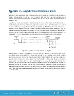
Page 20: ...he character is defined by the transmission of a pre defined number of stop bits usually 1 1 5 or 2 An extra bit used for error detection is often appended before the stop bits Figure 9 Asynchronous Communications Bit Diagram This special bit is called the parity bit Parity is a simple method of determining if a data bit has been lost or corrupted during transmission There are several methods for ...

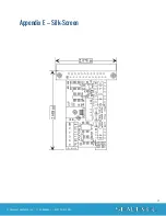
Page 21: ...21 Sealevel Systems Inc 1102 Manual SL9135 6 2021 Appendix E Silk Screen ...

Page 22: ...d to correct the interference at the user s expense EMC Directive Statement Products bearing the CE Label fulfill the requirements of the EMC directive 89 336 EEC and of the low voltage directive 73 23 EEC issued by the European Commission To obey these directives the following European standards must be met EN55022 Class A Limits and methods of measurement of radio interference characteristics of...

Page 23: ...nty Warranty service may be obtained by delivering the Product to Sealevel and providing proof of purchase Customer agrees to ensure the Product or assume the risk of loss or damage in transit to prepay shipping charges to Sealevel and to use the original shipping container or equivalent Warranty is valid only for original purchaser and is not transferable This warranty applies to Sealevel manufac...

Reviews: