background image

MIL-188 SPECIFICATIONS


Voltage levels 


MIL-188-C single ended input uses positive true logic.  The normally idle, or marking, line is 
represented as +5 volts output.  The start bit, or space condition, causes the output to switch 
to -5 volts. 


MIL-188-114 differential transmission utilizes two wires per signal. Signal voltage is at +5, 
while the other signal voltage is at -5 volts. 

LINE TERM INATION 


Each receiver is terminated in a 180 ohm resistor.  The drivers have 10 ohm current limiting 
resistors in series with the output signal for protection.   
 

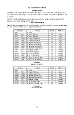
SIGNAL  

NAME 

PIN # 

MODE 

GND 

Ground 


RDB 

RX+ 

Receive Positive 

16 

Input  

RDA 

RX- 

Receive Negative 

Input  

CTSB 

CTS+ 

Clear To Send Pos. 

13 

Input  

CTSA 

CTS- 

Clear To Send Neg. 

Input  

DSRB 

DSR+ 

Data Set Ready Pos. 

22 

Input  

DSRA 

DSR 

Data Set Ready Neg. 

Input  

DCDB 

DCD+ 

Data Carr. Detect Pos. 

10 

Input  

DCDA 

DCD- 

Data Carr. Detect Neg. 

Input  

TDB 

TX+ 

Transmit Positive 

14 

Output  

TDA 

TX- 

Transmit Negative 

Output  

RTSB 

RTS+ 

Req. To Send Pos. 

19 

Output  

RTSA 

RTS- 

Req. To Send Neg. 

Output  

DTRB 

DTR+ 

Data Term. Ready Pos. 

23 

Output  

DTRA 

DTR- 

Data Term. Ready Neg. 

20 

Output 


FIGURE 5 

MIL-188-114 PIN-OUT


SIGNAL  

NAME 

PIN # 

MODE 

GND 

Ground 


RDB 

RX+ 

Receive Positive 

16 

Input  

CTSB 

CTS+ 

Clear To Send Pos. 

13 

Input  

DSRB 

DSR+ 

Data Set Ready Pos. 

22 

Input  

DCDB 

DCD+ 

Data Carr. Detect Pos. 

10 

Input  

TDB 

TX+ 

Transmit Positive 

14 

Output  

RTSB 

RTS+ 

Req. To Send Pos. 

19 

Output  

DTRB 

DTR+ 

Data Term. Ready Pos. 

23 

Output  


FIGURE 6 

MIL-188-C PIN-OUT 


Summary of Contents for MIL-188-C

Page 1: ...CIFICATIONS 6 WARRANTY FIGURES 1 ADDRESS SELECTION TABLE 2 DIP SWITCH ILLUSTRATION 3 HEADER E2 IRQ ILLUSTRATION 4 HEADER E4 MULTI IRQ ILLUSTRATION 5 MIL 188 114 PIN OUT 6 MIL 188 C PIN OUT 7 SILK SCRE...

Page 2: ...DRESS BINARY SWITCH POSITION SETTING Hex A9 A0 1 2 3 4 5 6 7 280 287 1010000XXX OFF ON OFF ON ON ON ON 2A0 2A7 1010100XXX OFF ON OFF ON OFF ON ON 2E8 2EF 1011101XXX OFF ON OFF OFF OFF ON OFF 2F8 2FF 1...

Page 3: ...all four jumpers Any other combination of jumpers i e one on three off is not a valid combination and can cause erratic data E2 These headers select the interrupt request for each serial port If COM1...

Page 4: ...allation For Windows Users Start by choosing Install Software at the beginning of the CD Choose Asynchronous COM Port Software SeaCOM Other Operating Systems Refer to the appropriate section of the Se...

Page 5: ...88 114 Serial Interface adapter Part 3202 provides one asynchronous serial port with the MIL 188 C Single Ended or MIL 188 114 Differential communications standard interface These interfaces are commo...

Page 6: ...X Receive Negative 3 Input CTSB CTS Clear To Send Pos 13 Input CTSA CTS Clear To Send Neg 5 Input DSRB DSR Data Set Ready Pos 22 Input DSRA DSR Data Set Ready Neg 6 Input DCDB DCD Data Carr Detect Pos...

Page 7: ...his period Sealevel Systems will at it s option replace or repair it at no additional charge except as set forth in the following terms This warranty does not apply to products damaged by misuse modif...

Reviews: