background image


25 

© Sealevel Systems, Inc.  5011 Manual   |   SL9167  12/2022 

Appendix C – Electrical Interface, Continued 


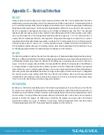
V.35 

V.35 is a standard defined by ITU (formerly CCITT) that specifies an electrical, mechanical, and physical 
interface that is used extensively by high-speed digital carriers such as AT&T Dataphone Digital Service 
(DDS). ITU V.35 is an international standard that is often referred to as Data Transmission at 48 Kbps using 
60 - 108 KHz Group-Band Circuits. ITU V.35 electrical characteristics are a combination of unbalanced 
voltage and balanced current mode signals. Data and clock signals are balanced current mode circuits. 
These circuits typically have voltage levels from 0.5 Volts to -0.5 Volts (1 Volt differential). The modem 
control signals are unbalanced signals and are compatible with RS-232. The physical connector is a 34 pin 
connector that supports 24 data, clock, and control signals. The physical connector is defined in the ISO-
2593 standard. ITU V.35 specification defines two types of interface circuits, Data Terminal Equipment 
(DTE) and Data Circuit-Terminating Equipment (DCE). The Sealevel Systems adapter is a DTE interface. 


Summary of Contents for Route 56

Page 1: ...1 Sealevel Systems Inc 5011 Manual SL9167 12 2022 Route 56 User Manual 5011...

Page 2: ...YOU GET STARTED 3 INTRODUCTION 4 CARD SETUP 5 INSTALLATION 8 TECHNICAL DESCRIPTION 9 SPECIFICATIONS 21 APPENDIX A TROUBLESHOOTING 22 APPENDIX B HOW TO GET ASSISTANCE 23 APPENDIX C ELECTRICAL INTERFAC...

Page 3: ...ions Warning The highest level of importance used to stress a condition where damage could result to the product or the user could suffer serious injury Important The middle level of importance used t...

Page 4: ...g data rates to reach 10M bps in burst mode By utilizing the Z16C32 s 32 byte FIFO buffer coupled with 256K of on board memory higher data rates are achieved without increasing processor overhead What...

Page 5: ...9 A8 A0 1 2 3 4 5 6 238 23F 1 000111XXX On On On Off Off Off 300 307 1 100000XXX Off On On On On On 308 30F 1 100000XXX Off On On On On On 310 317 1 100010XXX Off On On On Off On 318 31F 1 100010XXX O...

Page 6: ...to the on position at a time The following example illustrates SW 2 When IFSEL 1 then the values read from M3 M0 are determined by values written to base 5 register If this method is utilized all swit...

Page 7: ...used to select the interrupt request for each the Route 56 In the example below IRQ12 is selected This setting must be made prior to installing the adapter Please query your system to determine the b...

Page 8: ...able provides a high quality shielded cable with the V 35 mechanical specification met on one end and a DB 25S female on the other end V 35 has a mechanical specification that is impossible to place o...

Page 9: ...seamless integration into any ISA based system The ROUTE 56 adapter requires a 80286 or higher CPU one IRQ a 8 byte block of I O address and a 16K block of memory address The memory range of this ada...

Page 10: ...10 Sealevel Systems Inc 5011 Manual SL9167 12 2022...

Page 11: ...built in DMA controller supports 4 different modes of DMA transfer Single Buffer Pipelined Array and Link List An on board 16MHz oscillator clocks the IUSC RAM The ROUTE 56 has 256K of on board SRAM...

Page 12: ...12 Sealevel Systems Inc 5011 Manual SL9167 12 2022...

Page 13: ...13 Sealevel Systems Inc 5011 Manual SL9167 12 2022...

Page 14: ...14 Sealevel Systems Inc 5011 Manual SL9167 12 2022...

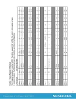
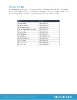
Page 15: ...16C32 user s manual If using a Sealevel Systems Inc supplied driver this is for informational use only Signal Source Transmit Data 16C32 TXD Pin Request To Send 16C32 Port7 Pin Data Terminal Ready 16C...

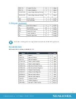
Page 16: ...2 Output RTS Request To Send 4 Output LL Local Loop back 18 Output RL Remote Loop back 21 Output Please terminate any control signals that are not going to be used The most common way to do this is co...

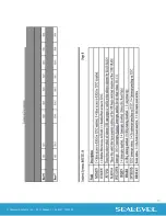
Page 17: ...Output All modem control signals are single ended un balanced with RS 232 signal levels RS 530 RS 422 DIP Switch SW2 2 or Base 5 M3 M0 D 1101 Signal Name Pin Mode GND Ground 7 RDB RX Receive Positive...

Page 18: ...18 Sealevel Systems Inc 5011 Manual SL9167 12 2022...

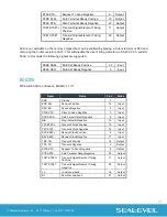
Page 19: ...A DSR Data Set Ready Negative 6 Input RS 530A DIP Switch SW2 3 or Base 5 M3 M0 F 1111 Signal Name Pin Mode GND Ground 7 RDB RX Receive Positive 16 Input RDA RX Receive Negative 3 Input CTSA CTS Clear...

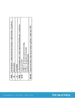
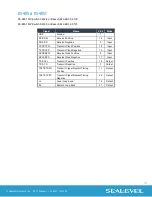
Page 20: ...Receive Negative 3 Input TXCB TXC Transmit Clock Positive 12 Input TXCA TXC Transmit Clock Negative 15 Input RXCB RXC Receive Clock Positive 9 Input RXCA RXC Receive Clock Negative 17 Input TDB TX Tra...

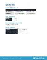
Page 21: ...C 4 to 158 F Humidity Range 10 to 90 R H Non Condensing 10 to 90 R H Non Condensing Power Requirements Supply line 5 VDC Rating 500 mA Mean Time Between Failures MTBF Greater than 150 000 hours Calcu...

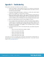
Page 22: ...ing an I O address and IRQ 4 Make sure the Sealevel Systems adapter is securely installed in a 16 bit slot 5 Use the supplied software and User Manual to verify that the Sealevel Systems adapter is co...

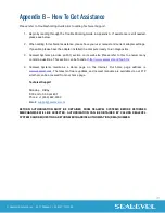
Page 23: ...FAQ section on its web site Please refer to this to answer many common questions This section can be found at http www sealevel com faq htm 4 Sealevel Systems maintains a Home page on the Internet Ou...

Page 24: ...s a differential interface that defines voltage levels and driver receiver electrical specifications On a differential interface logic levels are defined by the difference in voltage between a pair of...

Page 25: ...cal characteristics are a combination of unbalanced voltage and balanced current mode signals Data and clock signals are balanced current mode circuits These circuits typically have voltage levels fro...

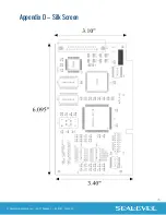
Page 26: ...26 Sealevel Systems Inc 5011 Manual SL9167 12 2022 Appendix D Silk Screen...

Page 27: ...to correct the interference at the user s expense EMC Directive Statement Products bearing the CE Label fulfill the requirements of the EMC directive 89 336 EEC and of the low voltage directive 73 23...

Page 28: ...nty Warranty service may be obtained by delivering the Product to Sealevel and providing proof of purchase Customer agrees to ensure the Product or assume the risk of loss or damage in transit to prep...

Reviews: