© Sealevel Systems, Inc.
- 15 -
SeaLINK User Manual
Only the ends of an RS-485 network should have the 120
Ω
terminating resistor.
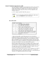
These resistors may be removed or inserted using the dipswitch ‘T’. This allows the
user to customize the electrical interface to their specific requirements. Each switch
position corresponds to a specific portion of the interface.
To add the termination/bias resistors, select the ‘On’ position, and to remove it, select
the ‘Off’ position. If multiple
adapters are configured in an RS-485 network, only the
boards on each end should have switches T, P & P ‘On’
.
The last option that is configurable via SW1 is the ‘Echo’ option (silk-screen ‘E’).
Two-wire RS-485 connects the TX
±
to the RX
±
. Every time a character is
transmitted it is also received. This can be beneficial if the software can handle
echoing (i.e. using received characters to throttle the transmitter), or it can confuse
the system if the software does not. Switch 9 is used to control the RS-485
enable/disable functions for the receiver circuit. To select the ‘No Echo’ mode set
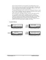
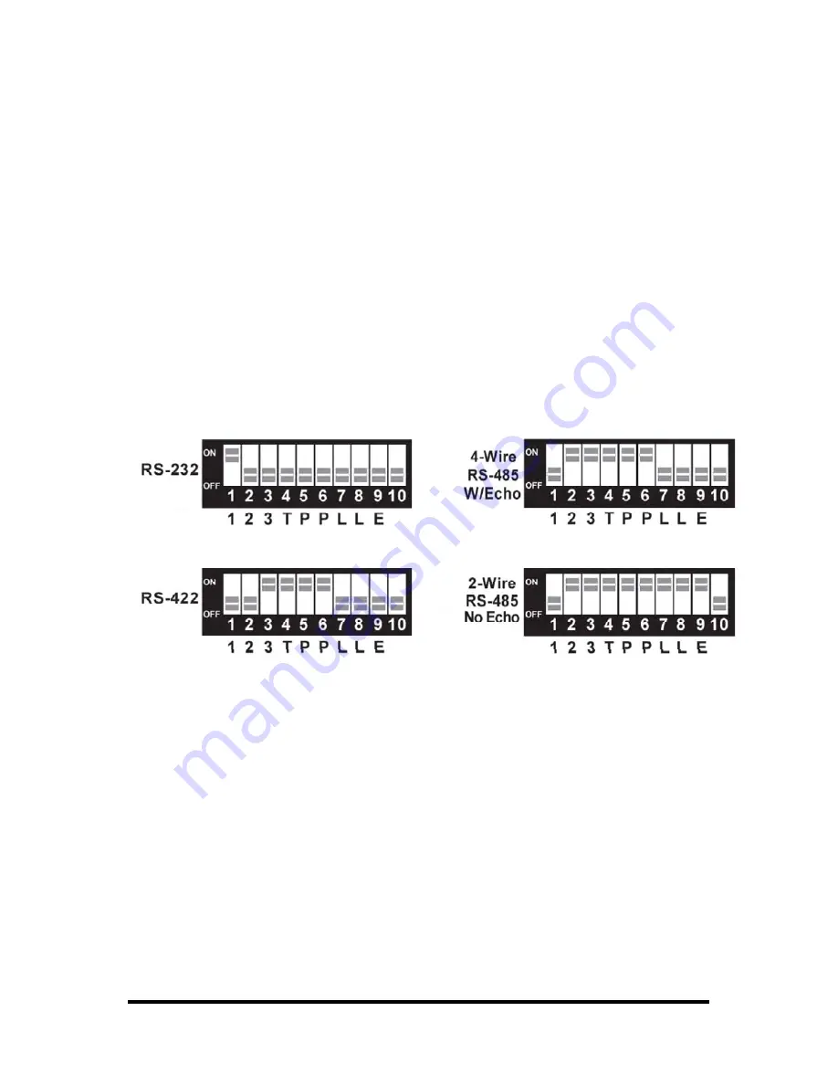
switch 9 to ‘On’. The following shows example switch settings.
Example Settings

