background image

© Sealevel Systems, Inc. 

- 75 - 

SeaLINK User Manual 


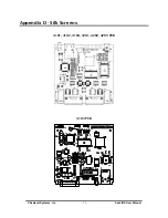
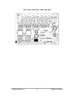
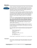
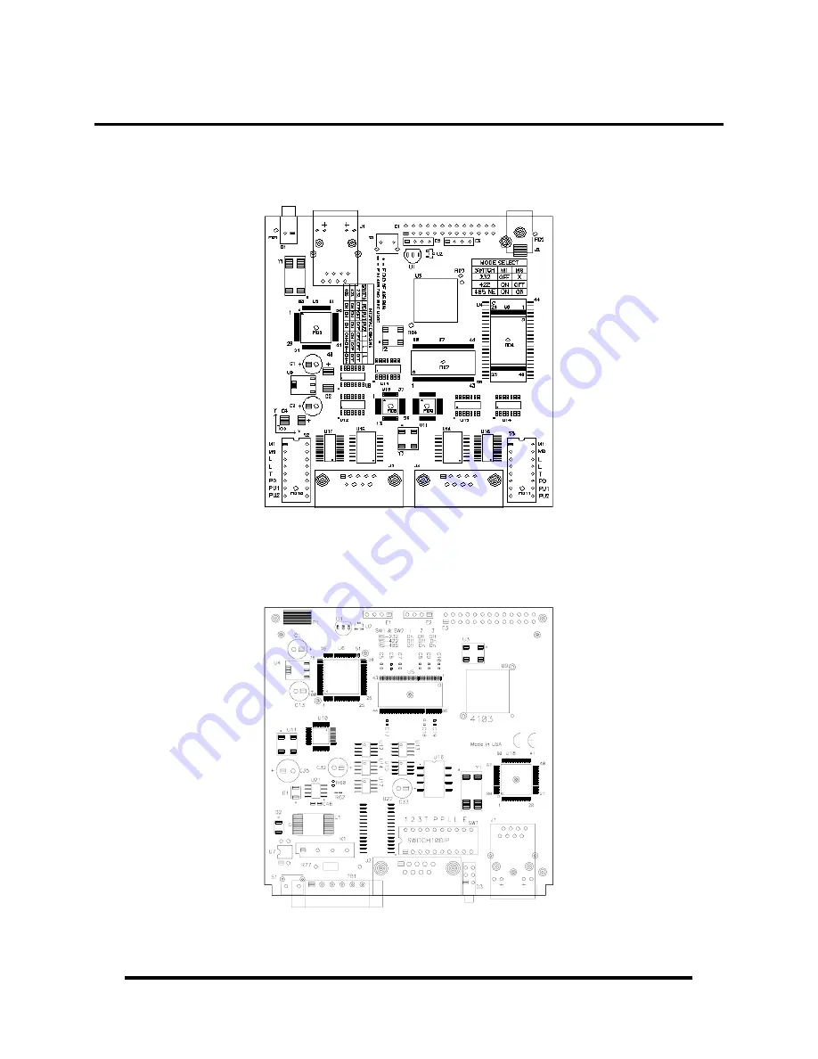
Appendix D - Silk Screens 


4101, 4102, 4104, 4201, 4202, 4203 PCB 


4103 PCB 


Summary of Contents for SeaLINK+2.232

Page 1: ...Sealevel Systems Inc www sealevel com SeaLINK User Manual SeaLINK User Manual Ethernet Serial Server Family...

Page 2: ...COM PORTS 19 DEVICE CONFIGURATION 21 SEALINK SOFTWARE INSTALLATION 22 PRE INSTALLATION CHECKLIST 22 WINDOWS 98 ME NT 2000 XP INSTALLATION 23 CREATE AND CONFIGURE SEALINK VIRTUAL COM PORTS 24 RAW DATA...

Page 3: ...ft Download Center For Windows 98 it is included in Internet Explorer 5 5 Internet Explorer 4 0 or later version 5 5 for Windows 98 4MB free space on hard drive Network requirements An Ethernet networ...

Page 4: ...2 Port RS 232 Serial Server SeaLINK 2 485 P N 4202 2 Port RS 422 485 Serial Server SeaLINK 2 Multi P N 4203 2 Port RS 232 422 485 Serial Server SeaLINK 4 232 P N 4401 4 Port RS 232 Serial Server SeaL...

Page 5: ...serial server listed below Replacement power supplies can be purchased from the Sealevel website Item TR101 5VDC 120VAC 3A power adapter Ships with 4401 4402 4403 4801 4802 and 4803 Item TR104 12VDC 1...

Page 6: ...ver cable 7 in length yellow RJ9P8 A modular adapter with an RJ45 female connector and a DB9 male connector Ships unassembled and can be easily configured without tools for virtually any pin out DB116...

Page 7: ...virtual COM port to host machine Data rates to 230 4K bps Hot swappable Built in watchdog reset circuit for fault tolerance Specifications Environmental Specifications Specification Operating Storage...

Page 8: ...S 422 485 serial server with DB 9M connector Configurable for RS 422 or RS 485 Automatic RS 485 enable disable SeaLINK Multi Item 4104 Features RS 232 422 485 serial server with DB 9M connector Config...

Page 9: ...or RS 232 RS 422 or RS 485 Automatic RS 485 enable disable Serial port is optically isolated Optically isolated digital input for monitoring 5V to 24V Reed relay output 60VDC 500mA max Power Requireme...

Page 10: ...serial server with DB 9M connectors Each port configurable for RS 422 or RS 485 Automatic RS 485 enable disable SeaLINK 2 Multi Item 4203 Features RS 232 422 485 serial server with DB 9M connectors Ea...

Page 11: ...eatures RS 422 485 serial server with DB 9M connectors Each port configurable for RS 422 or RS 485 Automatic RS 485 enable disable SeaLINK 4 Ultra Item 4403 Features RS 232 422 485 serial server with...

Page 12: ...Features RS 422 485 serial server with DB 9M connectors Each port configurable for RS 422 or RS 485 Automatic RS 485 enable disable SeaLINK 8 Ultra Item 4803 Features RS 232 422 485 serial server with...

Page 13: ...able for RS 422 or RS 485 Automatic RS 485 enable disable Transmit Receive LEDs on each RJ45 port Standard 19 rack enclosure SeaLINK 16 Ultra Item 4163 Features RS 232 422 485 serial server with RJ45...

Page 14: ...changing configuration options through the onboard web server The electrical interface RS 232 RS 422 or RS 485 for each port must be set properly in both places The hardware default is RS 422 mode Thi...

Page 15: ...One of the unique features of SeaLINK devices is the ability to be RS 485 compatible without the need for special software or drivers RS 485 auto enable Typically each end of the RS 485 bus must have...

Page 16: ...peration 9 E On for No Echo Off for Echo 10 Not Used A dipswitch labeled SW1 on the PCB provides the 4103 with the ability to communicate with RS 232 RS 422 or RS 485 devices The switch is also used t...

Page 17: ...ultiple adapters are configured in an RS 485 network only the boards on each end should have switches T P P On The last option that is configurable via SW1 is the Echo option silk screen E Two wire RS...

Page 18: ...CTS circuit Compensates for RS 232 biasing 6 T Adds or removes the 120 termination 7 PD Adds or removes the 1K pull down resistor in the RS 422 485 receiver circuit Receive data only 8 PU Adds or rem...

Page 19: ...a specific portion of the interface Each group of four switches controls one serial port refer to PCB for port numbers To add the termination bias resistors select the On position and to remove it sel...

Page 20: ...256 virtual COM ports from COM1 to COM256 Applications on the local computer can open virtual COM ports to use multiple networked serial devices at the same time The redirector handles each active vir...

Page 21: ...ws operating system provides Windows COM ports that applications use for input output and control operations that reach through the serial cable to the device Serial Servers If a PC is running more th...

Page 22: ...er Connections are established just as if the device were connected directly to the PC rather than over the network Benefits of Shared COM Ports There are two primary benefits to a serial server based...

Page 23: ...Windows device configuration is performed through the SeaLINK Config utility provided with the software installation When started the utility will display all devices on the local network the utility...

Page 24: ...l server are ready for SeaLINK You are using an Intel compatible PC with a Pentium class CPU running Windows 98 ME NT 4 0 SP6 2000 XP SP1 or Server 2003 Your PC has at least 4 megabytes of local disk...

Page 25: ...t and installation begins 7 A screen may appear with the declaration The publisher cannot be determined due to the problems below Authenticode signature not found Please select the Yes button and proc...

Page 26: ...follow the same naming numbering convention as Windows COM ports In this step you tell SeaLINK which serial ports to create as virtual COM ports 1 Launch the SeaLINK Config utility Start Programs SeaL...

Page 27: ...Manual 3 Select the serial ports you wish to map and press the Add button or you can press the Add All button to map all the available serial ports 4 In the Local Virtual COM Port listing select a st...

Page 28: ...nstall the correct modem driver for each new virtual COM port used by a modem This is explained in detail in the Create Modem Devices section of this manual The next page explains how to test your new...

Page 29: ...ows or type in the COM number you created with the SeaLINKConfig utility 5 Click on the Loopback tab and click the Start button in WinSSD 6 Click on the Help button on each tab of the WinSSD utility f...

Page 30: ...ove a virtual COM port select the ports you want to remove and click the remove button or click the remove all button to un map the virtual COM ports In the example from above virtual COM ports 3 and...

Page 31: ...up Click on the Cleanup button just above the Summary button shown on the previous page to fix the broken COM8 assignment from the example above In the example shown below the Virtual COM Port Cleanup...

Page 32: ...vice responds on the network Contact your network administrator for more information After updating your configuration click Apply Network Settings Changes to enable the new configuration Firmware Upd...

Page 33: ...and removes all SeaLINK virtual COM ports for your PC Follow these easy steps Run Add Remove Programs in the Control Panel Select SeaLINK Version 4 5 from the list of installed software Click the Add...

Page 34: ...equire dynamic serial port control Raw Data may be the most efficient choice for you 1 Configuration Since Raw Data does not allow for programmatic changing of serial port controls the serial ports mu...

Page 35: ...can be used to determine the IP address The web interface provides three separate pages selectable by tabs on the left side of the screen A Summary page lists various details about the device a Port S...

Page 36: ...ation page Gateway Default is not set A Gateway is a point of entry to and from an Ethernet network a node that translates between two different networks or network segments Netmask Default is not set...

Page 37: ...ch as SeaLINK software application programs may change these settings dynamically after opening the ports If you want to prevent programs from changing these settings click the Always use defaults che...

Page 38: ...ally configurable Protocol Ignored Modbus RTU Enable if communicating with Modbus serial COM devices When enabled the SeaLINK device won t transmit until a full Modbus packet has been received which h...

Page 39: ...t mapping and the numbers increment by one with the 16th serial port always being TCP port socket 4696 For example if you have a serial device connected to the 4th serial port of a SeaLINK 4401 four p...

Page 40: ...Administration page is where you can set general SeaLINK device settings You can set the device name IP address Gateway network mask timeouts etc You can set a password to prevent unauthorized access...

Page 41: ...tocol associated with it and accepts standard TCP IP socket connections Timeouts Allow new connection if existing has been idle x seconds 30 SeaLINK devices automatically prevent multiple users from o...

Page 42: ...work Mask if required Addressing DHCP or Static IP Address Text box Gateway Text box Netmask Text box Security Settings You can assign a password to the SeaLINK device to prevent unauthorized configur...

Page 43: ...n marked Reset to Factory Defaults For the username enter debug In the password field type in the MAC address no dashes or spaces of the unit located either on the summary page or on the label on the...

Page 44: ...HyperTerminal and many other applications can and sometimes must use Windows modem devices If your application needs a specific modem device as opposed to a COM port follow the instructions here to cr...

Page 45: ...ll list these during the process of creating the modem device Standard modems and generic drivers should be avoided 3 Open the Windows Control Panel and click on the Modems file or icon 4 Click Add to...

Page 46: ...D diagnostic utility WinSSD is part of the SeaLINK software suite and is included with the installation Using WinSSD 1 SeaLINK devices purchased from Sealevel ship with a serial loopback adapter See t...

Page 47: ...ost common way to do this is connect RTS to CTS and RI Also connect DCD to DTR and DSR Terminating these pins if not used will help ensure you get the best performance from your adapter RS 422 485 DB9...

Page 48: ...st To Send Negative Output 8 CTS Clear To Send Negative Input 9 CTS Clear To Send Positive Input Technical Note Please terminate any control signals that are not going to be used The most common way t...

Page 49: ...t used will help ensure you get the best performance from your adapter Optional Accessories Sealevel offers a modular adapter item RJ9P8 with an RJ45 female connector and a DB9 male connector This mod...

Page 50: ...modular adapter can be connected to any serial peripheral device with a DB9 connector which allows standard network patch cables to be used to connect the serial device to the serial server The Seale...

Page 51: ...t open a virtual COM connection to the serial port and toggle the DTR signal Refer to the Onboard Web Server section of this manual for instructions on configuring the device via the onboard web serve...

Page 52: ...function The CEthernet Development Libraries support the SeaI O Digital I O E series and SeaLINK Ethernet Serial Servers product families The source code contained in this document is designed to offe...

Page 53: ...thernet Library co exists with other libraries such as SeaLINK to communicate with Ethernet enabled devices As stated in the introduction this is a supplementary library and is not required for the de...

Page 54: ...hernet CCEthernet Alloc in number int find_devices in type_to_find ceth_device_type in number_to_find int inout list_to_store_devices ceth_device Free inout list ceth_device get_number_of_interfaces i...

Page 55: ...noted by the is defined by which command parameter is passed in The commands can be logically OR d together to make the sequence easier First each command individually SetIPAddress New IP Address New...

Page 56: ...locating memory Free Parameters list Pointer to the list previously allocated Return Values None NOTE Because the allocation masks much of the socket communication the interface provides a mechanism t...

Page 57: ...ply include the CEthernet lib file is contained on the link tab settings for the project Required Code For all of the following examples the following must be in either the StdAfx h file if using Prec...

Page 58: ...IO Ethernet c type SeaLink_Dev SeaLink Device Who Knows printf Mac 2 2X 2 2X 2 2X 2 2X 2 2X 2 2X n c mac_address c 0 c mac_address c 1 c mac_address c 2 c mac_address c 3 c mac_address c 4 c mac_addre...

Page 59: ...es If the return code is greater than zero then the function successfully found the number of devices returned Notice that we have to explicitly Free the allocated buffers and then delete the class fo...

Page 60: ...o is pass data between the PC and the device When you suspect problems lie with SeaLINK configuration first consider whether the types of problems that are occurring would happen if a faulty device ca...

Page 61: ...54 are accessible in this subnet which is specified in the second route listed The first route is the default route which specifies that all other address outside the range of the 10 0 0 x subnet be d...

Page 62: ...ess Netmask Gateway Interface Metric 0 0 0 0 0 0 0 0 10 23 0 1 10 23 0 135 1 0 0 0 0 0 0 0 0 10 0 0 1 10 0 0 47 2 The crux of the problem is this with the above routing table all packets outside the r...

Page 63: ...n for the gateway In the second case sometimes the backup gateway address is not online In either situation you will see connection errors occur in the Configuration Wizard even when you have specifie...

Page 64: ...n to determine that the 10 100 Base T connections and the polarity are correct If the Ethernet LED is lit you have a working Ethernet connection 4 Verify that the correct cable is being used i e Strai...

Page 65: ...the Port Information tab click the arrows or type in the COM number you created with the SeaLINKConfig utility 5 Click on the Settings button On the next screen click on the Restore Defaults button wh...

Page 66: ...OTE Any port number not in this range is incorrect and must be changed If more information is necessary see the Wizard Status and Error Messages section of this manual 3 Verify the make and model of W...

Page 67: ...d succeeds This problem is caused by the device group containing bad entries such as non existent ports malfunctioning devices devices that are turned off or devices with faulty connections to the tel...

Page 68: ...port number set for this SeaLINK COM port 2 Normal progress messages When the Wizard s work proceeds normally the messages summarize the interaction with the server These messages include Connected t...

Page 69: ...the Wizard does not see output that matches expected modem behavior it will report a modem detection problem with the Status panel containing one of the following messages Could not elicit AT OK resp...

Page 70: ...t port number 2 NETUNREACH TIMEDOUT or HOSTUNREACH Most likely cause The IP address number is incorrect 3 NAMETOOLONG AFNOSUPPORT Most likely cause The IP address as entered is a malformed hostname 4...

Page 71: ...able tracing as described above 3 Recreate the problem condition that you are debugging 4 Allow the Trace Window to show and record the history of communications activity between SeaLINK and the seria...

Page 72: ...in hour minute second millisecond format and the COM port where the event occurred There are three types of events 1 Transmit events Shown in green and preceded by these indicate that the application...

Page 73: ...ll not be able to use the server until the problem is resolved Contact your system administrator for help 2 Using route to check the routing table SeaLINK uses the route command to read and sometimes...

Page 74: ...Then check for the OK response from the modem AT typed by you might not echo as in the example below OK response from the modem The OK response indicates that the server has provided access to a mode...

Page 75: ...window session open you can type ATV1 to turn on text messages Verifying the creation of SeaLINK COM ports in Windows 98 Me NT If you are running Windows 98 ME or NT you can verify the presence of Se...

Page 76: ...eastern time Technical support can be reached at 864 843 4343 Technical Support 1 When calling for technical assistance please have your user manual and current serial server settings If possible ple...

Page 77: ...Sealevel Systems Inc 75 SeaLINK User Manual Appendix D Silk Screens 4101 4102 4104 4201 4202 4203 PCB 4103 PCB...

Page 78: ...Sealevel Systems Inc 76 SeaLINK User Manual 4401 4402 4403 4801 4802 4803 PCB...

Page 79: ...Sealevel Systems Inc 77 SeaLINK User Manual 4161 4162 4163 PCB...

Page 80: ...irective Statement Products bearing the CE Label fulfill the requirements of the EMC directive 89 336 EEC and of the low voltage directive 73 23 EEC issued by the European Commission To obey these dir...

Page 81: ...authorization must be obtained from Sealevel Systems before returned merchandise will be accepted Authorization is obtained by calling Sealevel Systems and requesting a Return Merchandise Authorizatio...

Reviews: