background image


14 

© Sealevel Systems, Inc.  2104 Manual   |  SL9092  9/2021 

Appendix C 

 Electrical Interface 

RS-422 

The RS-422 specification defines the electrical characteristics of balanced voltage digital interface circuits. 
RS-422 is a differential interface that defines voltage levels and driver/receiver electrical specifications. On 
a differential interface, logic levels are defined by the difference in voltage between a pair of outputs or 
inputs. In contrast, a single ended interface, for example RS-232, defines the logic levels as the difference 
in voltage between a single signal and a common ground connection. Differential interfaces are typically 
more immune to noise or voltage spikes that may occur on the communication lines. Differential interfaces 
also have greater drive capabilities that allow for longer cable lengths. RS-422 is rated up to 10 Megabits 
per  second  and  can  have  cabling  4000  feet  long.  RS-422  also  defines  driver  and  receiver  electrical 
characteristics that will allow 1 driver and up to 32 receivers on the line at once. RS-422 signal levels range 
from 0 to +5 volts. RS-422 does not define a physical connector. 


RS-485 

RS-485  is  backwardly  compatible  with  RS-422;  however,  it  is  optimized  for  party  line  or  multi-drop 
applications.  The  output  of  the  RS-422/485  driver  is  capable  of  being 

Active

  (enabled)  or 

Tri-State


(disabled). This capability allows multiple ports to be connected in a multi-drop bus and selectively polled. 
RS-485 allows cable lengths up to 4000 feet and data rates up to 10 Megabits per second. The signal levels 
for RS-485 are the same as those defined by RS-422. RS-485 has electrical characteristics that allow for 32 
drivers  and  32  receivers  to  be  connected  to  one  line.  This  interface  is  ideal  for  multi-drop  or  network 
environments. RS-485 tri-state driver (not dual-state) will allow the electrical presence of the driver to be 
removed from the line. Only one driver may be active at a time and the other driver(s) must be tri-stated. 
RS-485 can be cabled in two ways, two wire and four wire mode. Two wire mode does not allow for full 
duplex communication and requires that data be transferred in only one direction at a time. For half-duplex 
operation, the two transmit pins should be connected to the two receive pins (Tx+ to Rx+ and Tx- to Rx-). 
Four wire mode allows full duplex data transfers. RS-485 does not define a connector pin-out or a set of 
modem control signals. RS-485 does not define a physical connector. 


Summary of Contents for SEALINK+485I

Page 1: ...1 Sealevel Systems Inc 2104 Manual SL9092 9 2021 SEALINK 485I User Manual 2104...

Page 2: ...ARE INSTALLATION 6 CONFIGURATION 8 TECHNICAL DESCRIPTION 10 SPECIFICATIONS 11 APPENDIX A TROUBLESHOOTING 12 APPENDIX B HOW TO GET ASSISTANCE 13 APPENDIX C ELECTRICAL INTERFACE 14 APPENDIX D GROUND LOO...

Page 3: ...422 485 Asynchronous serial port providing a versatile interface for common RS 422 485 needs The SeaLINK 485I connects through the PC s external USB port so it does not require opening the computer c...

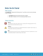
Page 4: ...g to Upstream Host Hub Advisory Conventions Warning The highest level of importance used to stress a condition where damage could result to the product or the user could suffer serious injury Importan...

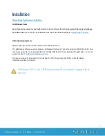
Page 5: ...Operating Systems Refer to the appropriate section of the Serial Utilities Software For additional software support please call Sealevel Systems Technical Support 864 843 4343 Our technical support is...

Page 6: ...switch for your specific application Please see the Configuration section for more information The SeaLINK 485I is defaulted to RS 422 mode so changes are only required if you will be using the produ...

Page 7: ...port by using the assigned COM identifier shown above In this case it is COM5 but this assignment will vary from system to system At this point the hardware is recognized To verify operation use Seal...

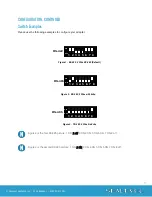
Page 8: ...position either enables adds or connects based on the function of the switch position listed below Switch SW1 position OFF disables removes or disconnects SW1 Function 1 RS 485 Two Wire Auto Enable Di...

Page 9: ...gure 2 is the first RS 485 picture 1 ON 2 off 3 ON 4 ON 5 ON 6 ON 7 ON 8 off Figure 3 is the second RS 485 picture 1 ON 2 ON 3 ON 4 ON 5 ON 6 ON 7 ON 8 off ON 1 2 3 4 5 6 7 8 OFF RS 422 Figure 1 RS 42...

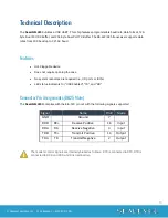
Page 10: ...opening the case No system resources are required i e I O ports or IRQ s LED status indicators for USB Enabled TD and RD Connector Pin Assignments DB25 Male The SeaLINK 485I complies with the EIA 530...

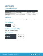
Page 11: ...ing Manufacturing All Sealevel Systems Printed Circuit boards are built to UL 94V0 rating and are 100 electrically tested These printed circuit boards are solder mask over bare copper or solder mask o...

Page 12: ...ED EN will be lit This should allow you to use Sealevel s WinSSD utility and the supplied loopback plug to check communications The supplied loopback plug connects TD to RD If you decide to test the M...

Page 13: ...an FAQ section on its web site Please refer to this to answer many common questions This section can be found at http www sealevel com faq asp Sealevel Systems maintains a web page on the Internet Our...

Page 14: ...or RS 485 RS 485 is backwardly compatible with RS 422 however it is optimized for party line or multi drop applications The output of the RS 422 485 driver is capable of being Active enabled or Tri St...

Page 15: ...t can cause equipment malfunction or even destruction Cabling Recommendations When connecting the SeaLINK 485I in an RS 485 network care should be taken that both ends of the network are not isolated...

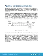
Page 16: ...of the character is defined by the transmission of a pre defined number of stop bits usually 1 1 5 or 2 An extra bit used for error detection is often appended before the stop bits Asynchronous Commu...

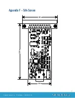
Page 17: ...17 Sealevel Systems Inc 2104 Manual SL9092 9 2021 Appendix F Silk Screen 3 28 in 2 09in 1 39in...

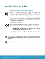
Page 18: ...to correct the interference at the user s expense EMC Directive Statement Products bearing the CE Label fulfill the requirements of the EMC directive 89 336 EEC and of the low voltage directive 73 23...

Page 19: ...ty Warranty service may be obtained by delivering the Product to Sealevel and providing proof of purchase Customer agrees to ensure the Product or assume the risk of loss or damage in transit to prepa...

Reviews: