


4. CONTROLS & SYMBOLS
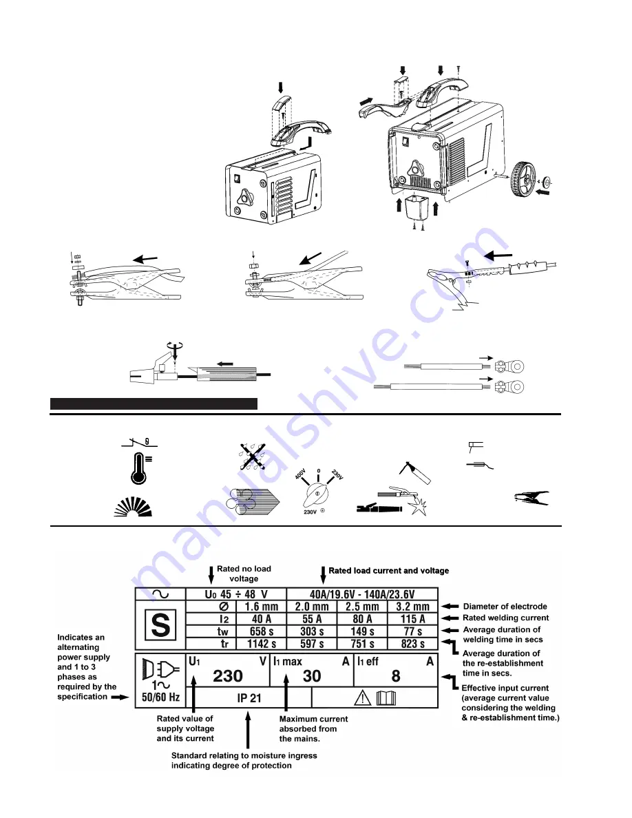
3.3.
Where necessary assemble wheels, handle & feet
according to the model supplied.(figs 1a,1b,)
3.3.
Where necessary assemble the work clamp supplied with your model to the cable associated with the work collet symbol as indicated below.
3.5.
Where necessary assemble the electrode holder supplied with your model to the cable associated with the manual arc welding symbol.
(see fig.3). On models with terminal style connections assemble eyelets to cables as shown in fig.3.
The following is to assist you identify your model’s control panel symbols.
ELECTRO-FAN
Cools the
machine when
running.
THERMOSTATIC
PROTECTION
Lights up when the
machine overheats
and cuts out. The
machine can be used
again when cooled.
SWITCH
POSITION
settings
EARTH
CLAMP
REGULATION
SCALE
RAIN WARNING
SYMBOL
DO NOT
use the
machine in the
rain or snow.
ELECTRODE HOLDERS
Various. The electrode holder
is connected to
the machine
via this
outlet,
Manual arc welder
Work Collet
Fig 3
Fig 1a
Fig 1b
Fig 2
GUIDE TO RATINGS
PLATE AND SYMBOLS
(For actual ratings of your model
refer to the front panel or top cover.)
FOR ANY FURTHER
CLARIFICATION OF
SYMBOLS REFER TO
BRITISH STANDARD
EN 60974-6
Arc Welders 150XL.V3,150XTC.V3,160XTC.V3,200XTC.V3 - 1 - 200707
Summary of Contents for 150XL.V3
Page 7: ......


