IMPORTANT: Before EACh use, check jack is in sound working order, use following list to form an habitual pre-check procedure.
Check items are not: broken, cracked, bent, malfunctioning, distorted, worn, loose, damage to welds, leaking, dirty, noisy or missing.
p
WARNING! DO NOT use jack if any suspect part is found, or if believed to have been subjected to abnormal load or
shock. Immediately remove from service and contact your authorised service agent.
6.. . . . . Handle
7.. . . . . Cylinder/Hydraulic unit
8.. . . . . Stopper rings and Cotter pins
9.. . . . . All nuts and bolts
10.. . . . All seals
1.. . . . . Saddle attachments
2.. . . . . Saddle base
3.. . . . . Saddle tilt handles
4.. . . . . Tilt mechanism
5.. . . . . Piston rod
11.. . . . Jack main frame
12.. . . . Pump handle.
13.. . . . Foot pumps
14.. . . . Swivel caster wheels
15.. . . . Ring chains, hooks & pins
p
WARNING! Failure to assemble the jack correctly may result in serious damage, personal or fatal injury.
unpack the product and check contents against the parts listed in these instructions. should there be any damaged or missing parts
contact your supplier immediately.
3.1.
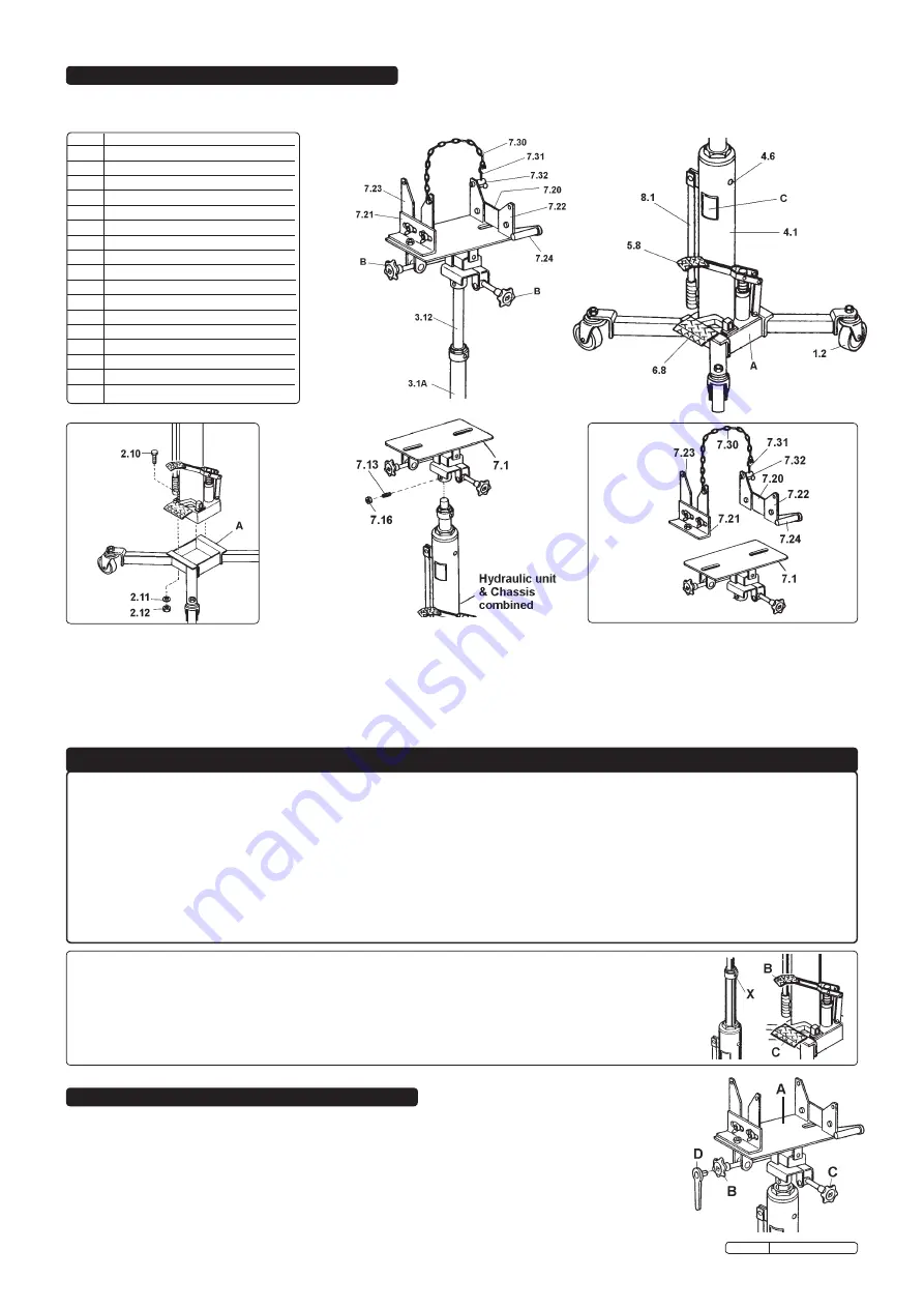
Attach power unit (fig.2) onto the chassis legs and castors (A) with assembly bolt (2.10), washer (2.11) and nut (2.12).
3.2.
Attach head plate assembly (fig. 3) with tilt mechanism (7.1) to upper end of hydraulic unit and chassis, and fix with pin bolt (7.13) & nut (7.16).
3.3.
Assemble saddle brackets (fig. 4, 7.20 to 7.24 & 7.30 to 7.32) to saddle base (7.1).
3. ASSEMBLY INSTRUCTIONS
4. PRE-USE CHECK LIST
1.2. swivel caster
3.1A. Piston rod (large)
3.12. Piston rod (small)
4.1. oil tank
4.6. oil filter plug
5.8. foot lifting pedal
6.8. foot lowering pedal
7.1. saddle base plate
7.18. saddle head tilt plate
7.20. saddle head bracket type ‘A’
7.21. saddle head bracket type ‘B’
7.22. saddle head attachment type ‘A’
7.23. saddle head attachment type ‘B’
7.24. saddle head attachment type ‘c’
7.30. ring chains
7.31. Hook with screw
7.32. Hook pin
8.1. Handle (transport)
IMPORTANT:
BEFORE THE FIRST USE OF JACK PURGE AIR FROM THE HYDRAULIC CIRCUIT.
Before using the jack for the first time, purge the hydraulic circuit in order to eliminate any air that may have
accumulated in the system during transit, as follows:
1.
check that pedal (c) is fully closed, and pump foot pedal (B) to raise saddle to the highest position.
2.
Loosen ‘air-purge’ plug (X) slowly. Depress foot pedal (B) several times until only oil seeps from the plug.
3.
close the plug and lower the jack by depressing foot pedal (c).
following will assist you identify operating parts. number reference in figs.1 to 4 correspond with spare parts list to assist with parts order.
notE: other diagrams use individual identification numbers or letters for ease of use, and do not correspond to fig.1, or part number list.
fig. 1
fig. 2
fig. 3
fig. 4
5. OPERATING INSTRUCTIONS
fig. 5
5.1.
SADDLE TILT MECHANISM.
Adjusting the pitch and tilt of saddle will assist you to safely support and transport the transmission.
the saddle (fig.5. A) may be tilted forward 30°, backward 15° by turning knob ‘B’ and to the left or
right 10° by turning ‘c’.
NOTE:
If tilt controls do not turn easily, insert ratchet wrench into hole in handles and rotate
accordingly (fig.5. D).
Original Language Version
500GtA Issue: 4 - 19/04/10


