Key 6. SPOT WELDING CURRENT SELECTION KEY
The welder has a programmed SKA valve suitable for a 1OKVA supply. If it is necessary to alter this setting (i.e. the machine
indicates low voltage), then it can be increased or decreased with this key before welding commences.
In order to program the current press key 8 (fig 5) for at least 5 seconds, to enter programming mode. Release key 8 and press key 7
to select required current (scale is marked in units of 1000Amps). Press key 8 for another 5 seconds to exit programming mode.
The lower the selected current the thinner the weldable sheet and the welder automatically indicates if the sheet thickness selected
exceeds that suitable for the programmed current.
Key 7. DOUBLE FUNCTION KEY.
Key 7 - as well as selecting welding current as above - will adjust spot welding time, (if necessary to deviate from the factory setting).
Key 8. DOUBLE FUNCTION KEY.
Key 8, if pressed for more than 5 seconds gives entry to, and exit from, the programming mode. It is also used to specify the thickness
of the sheet to be welded. If the LED corresponding to the selected thickness flashes, then the programmed current is insufficient to
weld such sheet correctly.
7. OPERATING INSTRUCTIONS
7.1.
PRELIMINARY CHECKS
7.1.1. General.
At the start of each work cycle it is important to perform the following checks before using the welder.
1. Check that the electrical connections are correct and fully plugged in.
2. When you use the pneumatic clamp, check the compressed air connections and
adjust the pressure regulator knob accordingly.
3. Manual clamp adjustment.
Position a shim (having the same thickness as the sheets to be welded) between
the electrodes. Ensure that, when the lever is operated the electrode arms are
parallel and the electrode holders are in line. Make adjustments by loosening the
locking screws on the electrode holders until you find the most suitable position for
the job to be performed, and re-tighten the locking screws. Adjust the force of the
electrodes during welding phase by adjusting the knurled nut (fig 6.A). Screw this nut
clockwise to increase the clamp force, but adjust so that clamp will close exerting
enough force to activates the microswitch (B).
7.1.2. Pneumatic Clamp Mechanical Adjustment.
1. Turn main switch ON
2. Position between the electrodes a shim of the same thickness as the sheet to be welded.
3. Press the clamp push-button to close the electrodes
4. Without any welding current:
Ensure that the electrode faces align squarely and adjust the arms if necessary. Tighten all adjustment locking screws.
The electrode lengths should be adjusted so that the clamp closes approx 8mm before clamping the sheets. This will ensure that
the correct clamping force is applied. The air pressure controls the clamping force and should be set at between 4 and 8 bar
(58 to 116psi). The required pressure will increase with sheet thickness and with electrode diameter.
7.2.
ACCESSORY LIST.
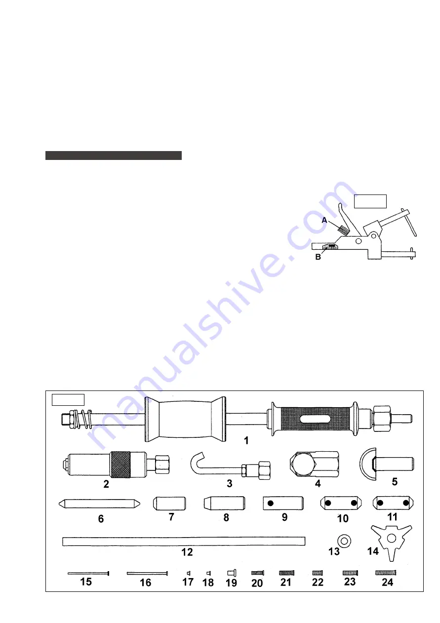
The following operational text will refer to figure 7 below for identification of component parts.
fig 7.
fig 6.
Electrospot 7000 - 0051 - (1) - 200999


