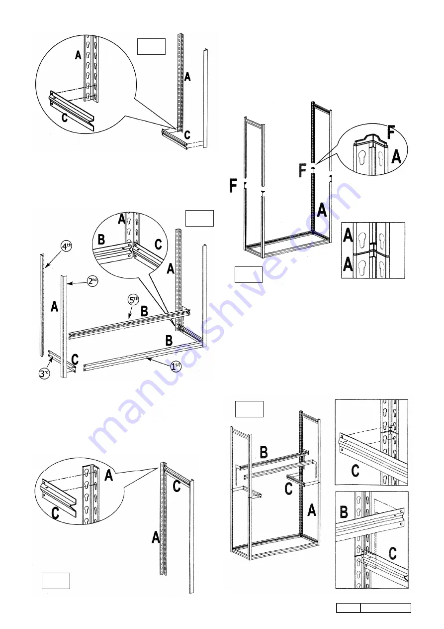
4.2 see fig.4.
support two upright angle posts (A) in a vertical
position ensuring that the keyhole slots are pointing downwards.
Join them together at the base using a short 'Z' beam (c)
ensuring that the shelf support is facing upwards. tap the beam
at either end, close to each angle post with a rubber mallet to
ensure that the rivets are seated at the bottom of the keyhole slots.
4.3 see fig.5.
continue to assemble the complete bottom frame in
the order indicated above in fig.5 starting with a long 'Z' beam (B).
Ensure that each 'Z' beam is facing upwards. tap the beam
at either end, close to each angle post with a rubber mallet to
ensure that the rivets are seated at the bottom of the keyhole slots.
4.4 see fig.6.
now make up an upper end frame by connecting two
angle posts together at the top with a short 'Z' beam (c). tap the
beam at either end to ensure that the rivets are properly seated.
at the botton of the keyhole slots. Make up a second upper end
frame using the remaining two angle posts and a short 'Z' beam.
4.5 see fig.7.
take the 4 post inserts (f) and push them into the top
of the four angle posts of the bottom frame assembly. now join
the two upper end frames to the bottom frame by mounting each
frame onto the post inserts as shown below.
4.6
see fig.8.
now stabilise the frame assembly by building a shelf
support halfway up the frame that joins together the upper and
lower parts of the frame. As each 'Z' beam is added ensure that
the top rivets are inserted into the bottom keyholes of the upper
frame and the lower rivets are inserted into the top keyholes of
the bottom frame as shown below. tap the beams at either end
with a rubber mallet to ensure that the rivets are properly seated
into the keyholes.
AP6548
IssuE no:1 26/06/08
fig.5
fig.4
fig.7
fig.8
fig.6


