3. SPECIFICATION
Model No: . . . . . . . . . . . . . . . . . .
BB1502
. . . . . . . . . . . . . . . . . . . . . .
BB2002
Motor Power: . . . . . . . . . . . . . . . .
370W
. . . . . . . . . . . . . . . . . . . . . . . .
550W
Supply: . . . . . . . . . . . . . . . . . . . . .
230V
. . . . . . . . . . . . . . . . . . . . . . . . . .
230V
No Load Speed: . . . . . . . . . . . . . .
2850rpm
. . . . . . . . . . . . . . . . . . . .
2850rpm
Spindle Size: . . . . . . . . . . . . . . . .13mm . . . . . . . . . . . . . . . . . . . . . . . . 16mm
Buffing/Polishing Wheel: . . . . . . .
Ø150x10xØ13mm
. . . . .
Ø200x14xØ16mm
Buffing Wheel - Fine: . . . . . . . . . .
BG150BW
. . . . . . . . . . . . . . . . .
BG200BW
Buffing Wheel - Coarse: . . . . . . . .
BG150BWC
. . . . . . . . . . . . . .
BG200BWC
Nett Weight: . . . . . . . . . . . . . . . . .
9kg
. . . . . . . . . . . . . . . . . . . . . . . . . . .
10kg
4. INSTALLATION
4.1.
Bolt the polisher securely to a workbench using the base securing holes as a template. Check that all assembly nuts and bolts
are secure before powering.
DO NOT
block the 4 motor ventilation paths through the base.
4.2.
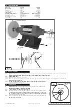
Wheel Fitting (fig.1)
4.2.1. Place the spacer over the axle shoulder.
4.2.2. Sandwich the selected buffing wheel between the clamp rings and secure with the hexagon nut, hand tight. (The axle threaded
ends are handed LH and RH).
4.2.3 Tighten the nuts enough to grip without crushing the buffing wheel. Wheel rotation,
in use, will tighten the hexagon nut.
5. OPERATION
WARNING!
Before commencing work, ensure you have read, understood,
and apply the chapter 1. Safety Instructions.
5.1.
Plug the polisher into the mains power supply.
5.2.
Switch the polisher on and bring the workpiece slowly into contact with the wheel.
The safest and best position for contact with the wheel is between “7-0-clock” and
the “8-0-clock” positions in (fig.2).
DO NOT
contact the wheel outside the quadrant
“6-0-clock” and “9-0-clock” positions.
5.3.
When completed, unplug the polisher from the mains power supply, and clean the
machine ready for next use.
B
B1502 & BB2002 | Issue 3 (U) 29/10/18
Original Language Version
© Jack Sealey Limited
"9"
"8"
"7"
Operator side
Direction of
rotation
Buffer Wheel
fig.2
RH THREAD END
LH THREAD END
"I/O" On/Off
Switch
M12 (Model No BB1502)
M16 (Model No BB2002)
Buffing wheel
Clamp ring
Spacer
Hex nut
RH/LH
Direction of rotation
Motor vent (4 sides)
fig.1


