4. grinding sTOnes
2. inTrOdUcTiOn & sPeciFicATiOns
3. AsseMbLY & insTALLATiOn
Model no:
bg150WL
bg150XWL
bg200WL
Motor: . . . . . . . . . . . . . . . . . . . . . . . . . . . . 250W . . . . . . . . . . . . . . . . . . . . . . . . . . . . . . 250W . . . . . . . . . . . . . . . . . . . . . . . . . . . . . 550W
input:. . . . . . . . . . . . . . . . . . . . . . . . . . . . . .230V . . . . . . . . . . . . . . . . . . . . . . . . . . . . . . . 230V . . . . . . . . . . . . . . . . . . . . . . . . . . . . . .230V
Axle Diameter: . . . . . . . . . . . . . . . . . . . 12.7mm . . . . . . . . . . . . . . . . . . . . . . . . . . . . .12.7mm . . . . . . . . . . . . . . . . . . . . . . . . . . . 15.8mm
Loaded With: . . . . . . . . . . . . . . . . . . 2 x Stones. . . . . . . . . . . . . . . 1 x Stone 1 x Wire Brush . . . . . . . . . . . . . . . . . . . . . . . . . 2 x Stones
no Load Speed: . . . . . . . . . . . . . . . . . .2850rpm . . . . . . . . . . . . . . . . . . . . . . . . . . . . 2850rpm . . . . . . . . . . . . . . . . . . . . . . . . . . .2850rpm
Stone Size: . . . . . . . . . . . . . Ø150 x 20 x 13mm. . . . . . . . . . . . . . . . . . . .Ø150 x 20 x 13mm . . . . . . . . . . . . . . . . . . Ø200 x 25 x 16mm
Wire Brush Bore Size: . . . . . . . . . . . . . . . . . n/a. . . . . . . . . . . . . . . . . . . . . . . . . . . . . . 13mm . . . . . . . . . . . . . . . . . . . . . . . . . . . . . . . n/a
Weight: . . . . . . . . . . . . . . . . . . . . . . . . . . 9.05kg . . . . . . . . . . . . . . . . . . . . . . . . . . . . . . .8.6kg . . . . . . . . . . . . . . . . . . . . . . . . . . . . . . 16kg
unpack the product and check contents. if there are any damaged or missing parts contact your supplier immediately.
WArning!
Before assembly check to ensure grinder is unplugged from mains.
3.1 eYeshieLd
3.1.1 Adjust eyeshields so that the perspex shield provides maximum protection against debris being thrown from the wheel.
3.2
TOOL resT
3.2.1 Tool rest should be adjusted to provide no more than a 2mm gap between the wheel and rest.
3.2.2 Turn wheel by hand to check that this distance remains true for the complete rotation.
3.3
sPArK ArresTOr
3.3.1 Adjust spark arrestor to ensure that the lower edge is no more than 2mm from the surface of the wheel.
3.4
WheeL dressing TOOL
3.4.1 Wheel dressing tool is removed by pulling from motor casing and placed on the tool rest. The rotating toothed wheels should be
placed in gentle contact with the grinding face of the wheel.
WARNING: Wheel dressing should only be carried out by a suitably trained and qualified person.
3.5 insTALLATiOn
3.5.1
Bolt the grinder securely to a fireproof workbench using the base securing slots as a template. check that all assembly
nuts and bolts are secure then read section 4 (grinding stones) before use.
dAnger OF Fire/eXPLOsiOn hAzArd
WArning! The grinding process can produce streams of sparks which are a potential source of ignition.
dO nOT use the grinder where there are flammable liquids, solids or gases.
dO nOT allow grinder sparks to make contact with the operator’s clothing or any other fabric such as cleaning rags. Fabrics contaminated with
flammable materials such as petrol, oil, grease, paint and solvents are a particular fire hazard.
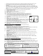
To reduce the risk of clothing catching fire the operator should wear wool or cotton outer garments treated with a fire retardant in preference to
man-made fibres.
Original Language Version
●
Induction motor drive.
●
fitted with stone guards, adjustable eyeshields and spark arrestors.
●
Equipped with fully CE approved safety guards and wheel location flanges to meet current EU abrasive wheel regulations.
●
Motor and switch gear
meet cE low voltage and EMc directives.
●
Fitted with a BS approved safety plug.
●
Flexible work light for added illumination.
●
Wheel dressing tool included.
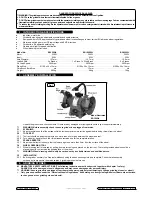
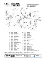
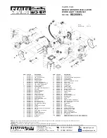
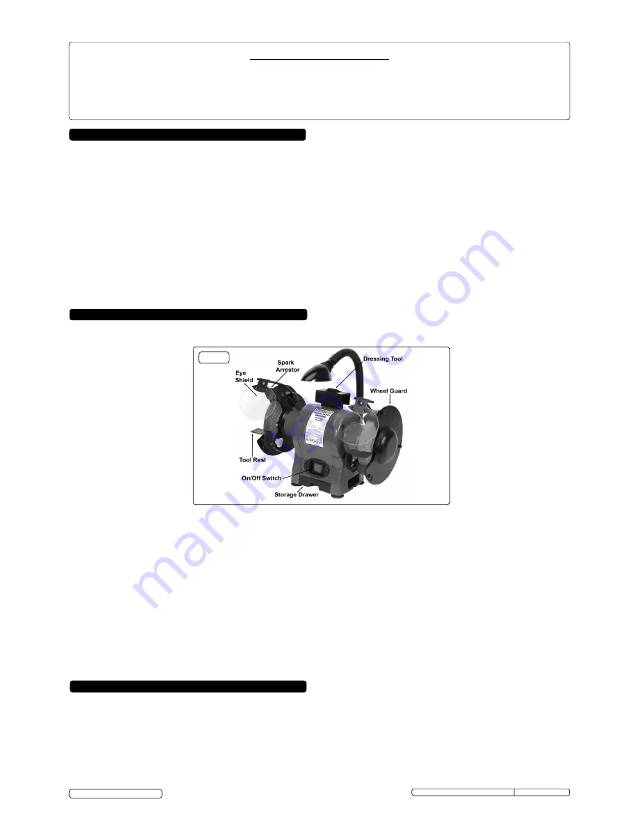
Fig.1
4.1 MAndATOrY sAFeTY insTrUcTiOns (The following instructions must be observed together with chapter 1 safety).
DANGER! Use of a damaged stone is dangerous and may cause damage and/or personal injury.
WARNING! Ensure grinder is unplugged from the mains power supply before attempting to change grinding stones (or wheel).
Only persons qualified under the “Abrasive Wheels Regulations” and holding a current grinding wheel certificate are authorised
to change and dress grinding stones (wheels).
BG150WL, BG150XWL & BG200WL issue: 1 - 22/11/12
© Jack Sealey Limited
Model illustrated:
bg150WL


