5.1
Pre-Use insPecTiOn
note: Use the same clearance and alignment information if your model has a wire brush.
WArning!
inSPEcT THE GrinDEr BEforE oPErATinG THE MAcHinE. EnSurE THE GrinDEr iS unPLuGGED froM
THE MAinS PoWEr BEforE coMMEncinG THE inSPEcTion.
5.1.1 check the tool rests are securely fixed and are set at a maximum of 2mm from the grinding stone.
5.1.2 check that eye shields are in good condition, are secure and that you can see through them clearly.
5.1.3 Turn the grinding stones by hand and check for any damage. check they do not touch the tool rests and are correctly aligned.
if any of the above checks fail, replace, repair, or adjust as necessary before starting the grinder.
5.2
sTOne Use
Depending on the model, grinders are supplied with one or two aluminous oxide stones. Stones have two grades, fine for hard
materials and coarse for soft materials.
When grinding, should surface of the stone become “loaded” (coated with particles of the material being ground) it is probably the
wrong grade of stone for the job.
IMPORTANT:
Grinding stones
MUST ONly
be assembled by a person holding a grinding wheel certificate. See section 4.
5.3
Using The grinder
WArning!
Before commencing work, ensure you have read, understood, and apply the chapter 1. Safety Instructions
5.3.1 Plug grinder into the mains power supply.
5.3.2 Place the eyeshield in its appropriate safety location.
5.3.3 Switch the grinder on and bring the workpiece slowly into contact with the spinning stone, or wire wheel.
5.3.4 When you have completed your task, unplug the grinder from the mains power supply, and clean the machine ready for next use.
6. MAinTenAnce
WArning!
Ensure the grinder is unplugged from the mains power supply before performing any maintenance or service.
6.1
As the grinding stone wears, adjust the position of the tool rests. The rest must be set at a maximum of 2mm from the stone surface.
6.2
regularly remove the grinding stone covers and clean out any dust and dirt.
6.3
The machine motor and bearing are sealed units and require no regular maintenance. Should you require assistance, contact your
local Sealey service agent.
6.4
for information relating to the handling and maintenance of grinding stones refer to section 4.
4.2
sTOne chAnging PrOcedUre
WArning!
Unplug grinder from the mains power supply before changing stone.
4.2.1 raise the eye shield up, and away from the stone.
4.2.2 remove tool rest.
4.2.3 remove the screws from the side of the wheel cover and remove the cover.
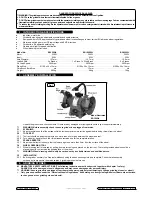
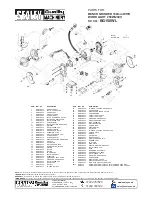
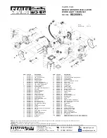
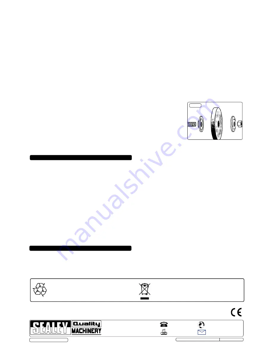
4.2.4 Hold grinding stone firmly. To protect your hands use cloth or wear gloves. unscrew retaining nut (fig 2.1.).
note:
The nut on the right side of the grinder has standard right hand thread (undo anti-clockwise). The left
side nut has a left hand thread and must be loosened by turning clockwise.
it may be necessary to strike
the wrench sharply in the loosening direction with the heel of your hand to loosen the nut.
4.2.5 remove grinding stone washer (fig 2.2), blotter (3), stone (4), 2nd blotter (5), washer (6) from
main spindle (7).
4.2.6 carefully inspect the new stone before installing to ensure there are no fissures, chips, or
cracks.
WARNING!
DO NOT USE A DAMAGED STONE.
4.2.7 inspect the blotters, if they are damaged replace them. The grinder must never be used without
blotters. Should you not have any available when you need to replace them, cut out a piece of
suitable cardboard the same shape for temporary use only.
4.2.8 install the new stone by reversing steps above. Ensure washers (2 & 6) are installed with the
flange on the outside, (i.e. the concave side against the blotter).
4.2.9 Hold stone steady and secure locking nut.
dO nOT
over tighten as this may crack the stone.
4.2.10 replace stone cover, re-adjust tool rest to a maximum of 2mm from stone face and
tighten securely.
note:
You do not require a certificate to change a wire wheel. Assembly is the same as with a stone.
5. OPerATing insTrUcTiOns
NOTE:
It is our policy to continually improve products and as such we reserve the right to alter data, specifications and component parts without prior notice.
iMPOrTAnT:
no liability is accepted for incorrect use of this product.
WArrAnTY:
Guarantee is 12 months from purchase date, proof of which will be required for any claim.
inFOrMATiOn:
for a copy of our latest catalogue and promotions call us on 01284 757525 and leave your full name and address, including postcode.
01284 757500
01284 703534
sales@sealey.co.uk
sole UK distributor, sealey group,
Kempson Way, Suffolk Business Park
,
Bury St. Edmunds, Suffolk,
iP32 7Ar
www.sealey.co.uk
Web
Original Language Version
BG150WL, BG150XWL & BG200WL issue: 1 - 22/11/12
Grinding stones (wheels) used with this machine must be of an adequate speed rating and suitable for the material to be ground.
Ensure the grinding stone’s maximum speed specification is higher than that indicated on the machine data plate.
Check grinding stone is secure, the stone is not worn or damaged and that there are no splits or cracks. If damaged replace
immediately.
Ensure replacement stone is not damaged in any way such as cracks, deformations or splinters etc. Also check the mounting flanges
to ensure they are not deformed, burred or chipped. Damaged items must
NOT
be used as they may cause irregular pressure on the
stone which may cause a stone to break.
DO NOT
over tighten a stone. Never tamper with a stone in order to adapt it to a different size
holder.
Install a new stone as in 4.2. Once mounted on the grinder test the stone before use by facing the grinder in a safe direction (point
away from yourself, others and vulnerable items) and run for a short time. Dress the stone if necessary.
© Jack Sealey Limited
Fig.2
environmental Protection.
recycle unwanted materials instead of disposing of them as
waste. All tools, accessories and packaging should be sorted,
taken to a recycle centre and disposed of in a manner which
is compatible with the environment.
Weee regulations.
Dispose of this product at the end of its working life in compliance
with the Eu Directive on Waste Electrical and Electronic Equipment.
When the product is no longer required, it must be disposed of in an
environmentally protective way. contact your local solid waste
authority for recycling information.


