© Jack sealey limited
Original Language Version
model
no
...........................................................BG200/99.V3
supplied
with
.........................................................2
x
stones
motor
Power
..................................................................600W
supply
..................................................................230V,
50Hz
Axle
diameter
..............................................................
16mm
no
load
speed
........................................................2850rpm Weight ............................................................................
20kg
unpack the product and check contents should there be any damaged or missing parts
contact your supplier immediately.
Warning!
Before
assembly check
to
ensure
grinder
is
unplugged
from
mains.
4.1.
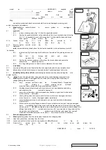
eyeshield.
4.1.1.
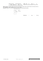
remove retaining screws (fig 1. A) from the eyeshield bracket.
4.1.2.
Position the eyeshield bracket on the underside of the stone cover and align holes (fig
2) 4.1.3. fix eyeshield to cover with screws (fig 2.1). if the shield is loose and drops
down, tighten
shield
screws
(fig
3.2)
4.1.4.
Loosen
screw
(fig
3.1.)
and
adjust
the
arrestor so
it
is
2mm
from
the
stone
face
(fig
4).
4.1.5.
Securely tighten
arrestor screw
(fig
3.1).
4.2.
tool rest.
note:
some models may already have the tool rest assembled, but stone clearance must still
be checked.
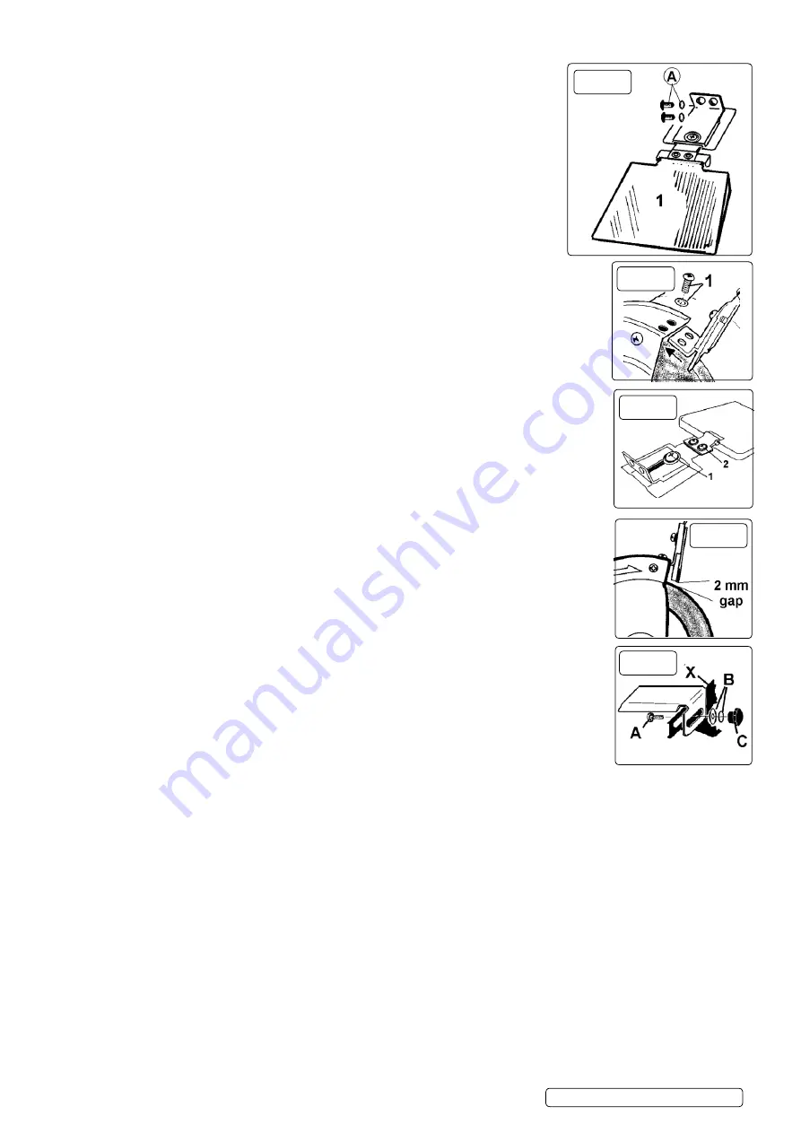
4.2.1.
take tool rest (fig 5) and align it with bolt slot on the inside of the grinding stone cover
(X).
4.2.2.
Pass
bolt
(A)
through both
slots
and
place
washers (B)
onto
bolt.
4.2.3.
Position the rest at a maximum of 2mm from the stone surface and secure the
assembly by
tightening knob (c).
4.2.4.
turn the grinding stones by hand to ensure clearance of above items.
4.3.
installation.
4.3.1.
securely bolt the grinder to a fireproof workbench using the base holes as a template. check
that
all assembly nuts and bolts are secure then read section 5 (grinding stones) before use.
5.1.
mandatOry Safety inStructiOnS.
(the following instructions must be observed together with
chapter 1 safety).
▲
danger!
use of a damaged stone is dangerous and may cause damage or personal injury.
Warning
! ensure grinder is unplugged from the mains power supply before attempting to
change grinding stones (or wheel).
5.1.1.
Only
persons qualified under
the
“Abrasive Wheels Regulations”
and
holding
a
current
grinding wheel
certificate
are authorised to change and dress grinding stones (wheels).
5.1.2.
Grinding stones (wheels) used with machine must be of an adequate speed rating
and suitable for the
material to be ground.
5.1.3.
ensure the cutting stone’s maximum speed specification is higher than that indicated
on the machine
data plate.
5.1.4.
check grinding stones are secure, and the stone is not worn or damaged, that there
are no fissures or cracks. if damaged replace immediately.
5.1.5.
ensure replacement stone is not damaged in any way such as cracks, deformations
or splinters etc.
5.1.6.
Also check the mounting flanges to ensure they are not deformed, burred or chipped. damaged
items
must
nOt
be used as they may cause irregular pressure on the stone which may cause
stone to break.
dO nOt
over tighten a stone. never tamper with a stone in order to adapt it to a
different size holder. 5.1.7.
install a new stone as in 5.2. once mounted on the grinder test the
stone before use by facing the
grinder in a safe direction (point away from yourself,
others and vulnerable items) and run for a short time. dress the stone if necessary.
5.2.
Stone changing procedure.
Warning!
unplug grinder from the mains power supply before changing stone.
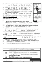
5.2.1.
raise the eye shield up, and away from the stone.
5.2.2.
loosen and pull the tool rest out as far as possible, but,
dO nOt
remove
it
(fig
6).
5.2.3.
Remove the
screws
from
the
side
of
the
wheel
cover
and
remove the
cover
(fig
6).
BG200/99.V3
|
Issue
1
19/12/16


