
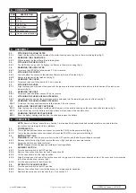

4. CONTENTS
5. ASSEMBLY
5.1.
ATTACHING THE FOAM FILTER
5.1.1.
Attach the foam filter to the underside of the motor housing, securing it onto the two retaining tabs (fig 3).
5.2.
REMOVING THE FOAM FILTER
5.2.1.
With care ease the foam filter off the retaining tabs.
5.3.
ATTACHING THE HEPA FILTER
5.3.1.
The HEPA filter is a push fit. Fully push the filter onto the motor housing (fig 4).
5.4.
REMOVING THE HEPA FILTER
5.4.1.
To remove the HEPA filter follow section 5.3 but in reverse.
5.5.
ATTACHING THE COVER
5.5.1.
Centrally place the cover with the attached filters onto the top of the tank (fig 5).
5.5.2.
Secure into place with the latch hooks (fig 5).
5.6.
REMOVING THE COVER
5.6.1.
To remove the cover follow section 5.5 but in reverse.
5.7.
ATTACHING THE HOSE
5.7.1.
Align the tongues on the end of the hose with the grooves in the tank suction inlet and turn in the direction of the lock arrow
indicator (fig 5).
5.8.
REMOVING THE HOSE
5.8.1.
To remove the hose follow section 5.7 but in reverse.
5.9.
ATTACHING THE HOSE NOZZLE EXTENSION
5.9.1.
Centrally insert one end of the metal hose nozzle extension into the remaining open end of the hose (fig 1).
5.10.
REMOVING THE HOSE NOZZLE EXTENSION
5.10.1.
T
o remove the hose nozzle extension follow section 5.9 but in reverse.
5.11.
INSTALLING THE BATTERY CARTRIDGE
5.11.1.
A
lign the tongue on the battery cartridge with the groove in the battery housing on the cover and slide into place (fig 5).
5.11.2.
Insert all the way until the battery cartridge is locked into position with an audible click.
5.12.
REMOVING THE BATTERY CARTRIDGE
5.12.1.
Push the battery cartridge latch button, the slide and remove the battery.
6. OPERATION
NOTE:
Ensure all Safety Instructions in Section 1 are read and fully understood and carried out before use and retain the
instructions and warnings for future reference.
6.1.
POWER SWITCH
6.1.1.
To turn the handheld ash vacuum cleaner on, press the
I
(ON) on the power switch (fig 6).
6.1.2.
To turn the handheld ash vacuum cleaner off, press the
O
(OFF) on the power switch (fig 6).
6.2.
EMPTING THE TANK
WARNING!
Ensure that the power switch is in the OFF position and the battery cartridge is removed.
6.2.1.
Release the latch clips (fig 5) and remove the cover (fig 5) and place in a secure location.
6.2.2.
Empty the ash into a suitable container.
NOTE:
Dispose of the ash properly according to local regulations.
6.3.
BLOWER FUNCTION
6.3.1.
Turn the power switch to the OFF position.
6.3.2.
Remove the suction hose from the tank. See section 5.8.
6.3.3.
Lift the carry handle into the raised position.
6.3.4.
Align the tongues on the end of the suction hose with the grooves in the tank cover, situated on top of the cover, and turn clockwise
to lock the suction hose in place (fig 6).
6.3.5.
Turn the power switch to the ON position.
6.4.
RETURN TO VACUUM FUNCTION
6.4.1.
Turn the power switch to the OFF position.
6.4.2.
Remove the suction hose, from the tank cover, by turning counter clockwise.
6.4.3.
Reattach the suction hose to the tank (fig 1). See section 5.7.
Original Language Version
© Jack Sealey Limited
ITEM
DESCRIPTION
1
Tank
2
Cover
3
HEPA Filter
4
Foam filter
5
Suction hose
6
Hose nozzle extension
fig.1
fig.2
C
P20VAV Issue 1 14/12/21


