
3. OPERATING INSTRUCTIONS
IMPORTANT WARRANTY INFORMATION:
the battery pack fitted to this cordless tool is considered to be a consumable item
and its ability to accept charge will reduce over time. We will warranty it against
mechanical and electrical defect for a period of one year - this does not cover fair
wear and tear. If the battery is not properly charged before first use, or regularly
conditioned, its capacity will diminish. under these circumstances we will not
replace the battery pack even if it is less than one year old.
3.1.
CHARGING THE BATTERY PACK.
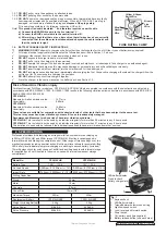
3.1.1. to remove the battery pack from the drill, depress the two side release buttons
(fig.2) and slide the drill off the battery pack.
WARNING! Do not touch the battery terminals.
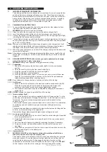
3.1.2. Place the drill in the carry case and remove the battery charger (fig.3).
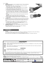
3.1.3. Invert the battery pack and slide onto the battery charger as shown in fig.4.
3.1.4. connect the charger to mains power and switch on. the red light (fig.3A) will light
indicating that the charge cycle has started.
3.1.5. the red light will remain on until the battery pack is fully charged when it will go out
and the green light (fig.3B) will go on. under normal conditions the battery will take
up to 1 hour to fully charge.
Note:
When new, the battery pack will have been shipped in a low charge state. It will
take longer to charge initially, and several subsequent charges may also take a
little longer, than when the battery pack reaches optimum performance.
3.1.6. When the green light comes on, switch off the charger, unplug from the mains and
remove the battery pack.
Note:
Attempting to recharge a battery pack
immediately
after use may result in the red
charge light not coming on. In such a case allow the battery to cool for a time and
try again.
3.2.
DRILLING INSTRUCTIONS.
(Ensure that you read, understand and comply
with all the Section 1 safety instructions)
WARNING!
Always wear approved safety glasses when drilling.
3.2.1.
Preparation.
1. check the drill to ensure the direction switch (fig.7A) is in the mid (locked)
position.
2. open the chuck by turning the front chuck collar (fig.5).
3. Insert the required bit fully into the chuck and tighten.
4. fit the battery pack to the drill handle.
5. Press the direction switch (fig.7A) in from the right, as you view drill from rear
(as held), for clockwise rotation, and press in from the left for anti-clockwise
rotation (withdrawing drill bits, undoing screws).
NOTE: Do not attempt to change direction of rotation while the drill is running.
3.2.2.
Drill Speed.
1. speed of the drill is controlled by the electronic variable speed switch (fig.7B).
Press the switch gently for a slow speed and progressively increase the
pressure on the switch to produce correspondingly higher speeds.
2. the maximum revolutions may also be adjusted by changing the two-speed
switch (fig.6).
NOTE: DO NOT change the speed range whilst the drill is running.
3.2.3.
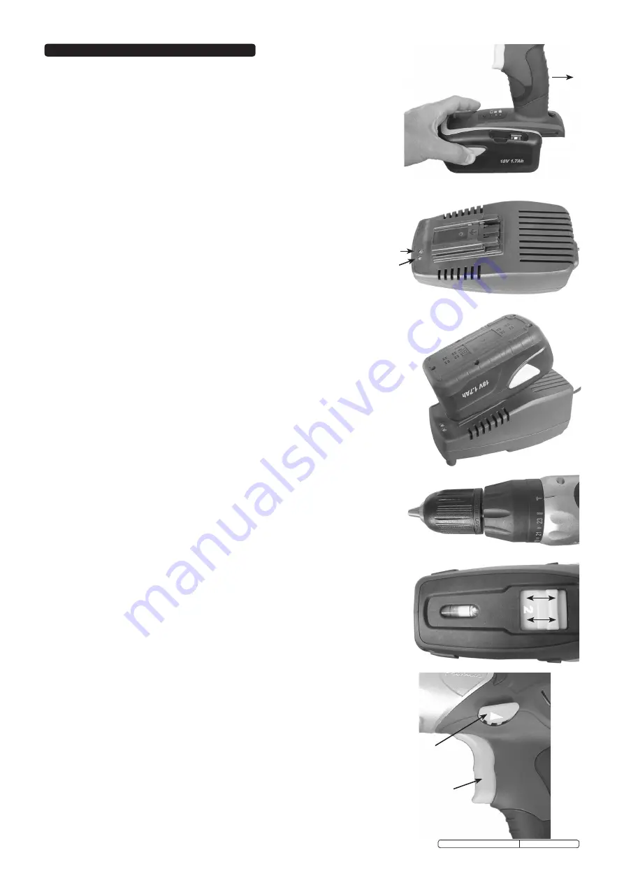
Torque setting. (fig.5)
torque is the amount of turning force applied by the drill. torque setting ‘1’ on the
control ring is the lowest and will apply the least effort - to the final turns of a screw,
for example. the torque becomes progressively greater with increased setting
numbers, up to 23.
the drill symbol position gives maximum torque with no clutch effect. the combination
of variable speed and variable torque gives maximum drilling/screw driving
efficiency.
the lower torque settings are suitable for driving small screws and drilling with fine
drill bits, to prevent shearing of the screws/bits.
screws/bits of larger diameter permit higher torque settings to be used.
3.2.4.
As a screw or bolt driver.
1. lock the appropriate tool bit in the chuck. select the shortest length bit possible
to ensure greatest control.
2. A small pilot hole may be required to ease the path of the screw, especially in
hard woods.
3. set a low torque to begin with, gradually increasing the torque if necessary.
4. to remove screws, press direction switch in from the left for reverse (anti-
clockwise).
5. When finished, remove the bit from the chuck, clean drill and bit and store in the
auxiliary handle (fig.8) or the battery pack.
3.2.5.
Hammer action.
WARNING! DO NOT use the hammer action with metal/wood drill bits as
these may shatter. Use only with masonry bits.
the hammer action, with a masonry drill bit, is used to assist drilling into concrete,
stone and masonry. to use the hammer function rotate the control ring (fig.5) to
select the the hammer symbol. to disengage the hammer function turn the
control back in the direction of the drill symbol on the control ring.
Note:
DO NOT
shift to ‘hammer’ when the drill is running as this may damage the machine.
fig.3
A
A
B
B
fig.4
fig.5
fig.6
fig.7
fig.2
Original Language Version
cP3014VHK, cP3018VHK Issue: 5 - 11/01/12


