3. BATTERY CHARGING
Note
:
When new, the batteries will have been shipped in a low charge state. Fully charge the battery before using your tool
3.1
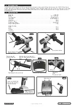
To remove the battery from the drill, see (Fig 6).
DO NOT
touch the metal battery terminals.
3.2
Take the base charger and plug it into the mains.
3.3
The battery is designed to fit into the charger one way only. This is to ensure that the positive (+) and negative (-) polarities correspond.
Insert the battery fully and firmly to
seat the battery into the charging base, as in (Fig.7).
3.4
When the battery is inserted into the charger the red LED (Fig.7) will illuminate, this indicates the battery is charging.
3.5
When the green LED illuminates (Fig.7) battery is fully charged. A one hour charge from flat; less from partially charged.
3.6
Remove the battery from the charger. Switch off and remove the plug from the mains. Push the battery back into the drill (Fig.6) until it
snaps into place. The drill is now ready for use.
Note:
A special feature of the battery is a "health" indicator scale of charge. Depress the battery symbol switch on the battery, a scale of
one to four green LED lights will illuminate see (Fig.1).
4. OPERATION
Note:
If the drill is overloaded during use a protection device will operate to prevent damage. To continue, release the trigger and press again.
4.1
With the drill in the locked mid position of the three position cw/mid locked/acw direction changer, see (Fig.2) legend item 9.
4.2
Open the chuck by holding the drill and rotating the knurled chuck collar in the direction marked "RELEASE" acw (Fig.5)
4.3
Insert the required drill/screw driver bit into the full length of the chuck and tighten by holding the drill and rotating the knurled chuck
collar in the direction marked "GRIP" cw (Fig.5).
4.4
Ensure correct drilling rotation direction by sliding the three position direction changer to the required position.
4.5
The speed of the drill is controlled by the drill trigger applied pressure, ranging from zero to maximum speed. This control is
independent of the "HI" and "LOW" speed sliding switch situated in the top of the drill body. The torch LED (Fig.5) also illuminates.
4.6
The torque setting "1" is minimum and "18" is maximum. A combination of variable speed and torque gives maximum drilling efficiency.
(Not available on hammer drill setting which has a fixed torque rating)
4.7
For task settings Drill or Hammer drill, see (Fig.4) icons.
4.8
On completion of tasks, remove bit from drill, clean all items and store in carry case.
1
2
4
4
5
6
7
3
8
9
10
12
11
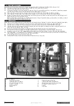
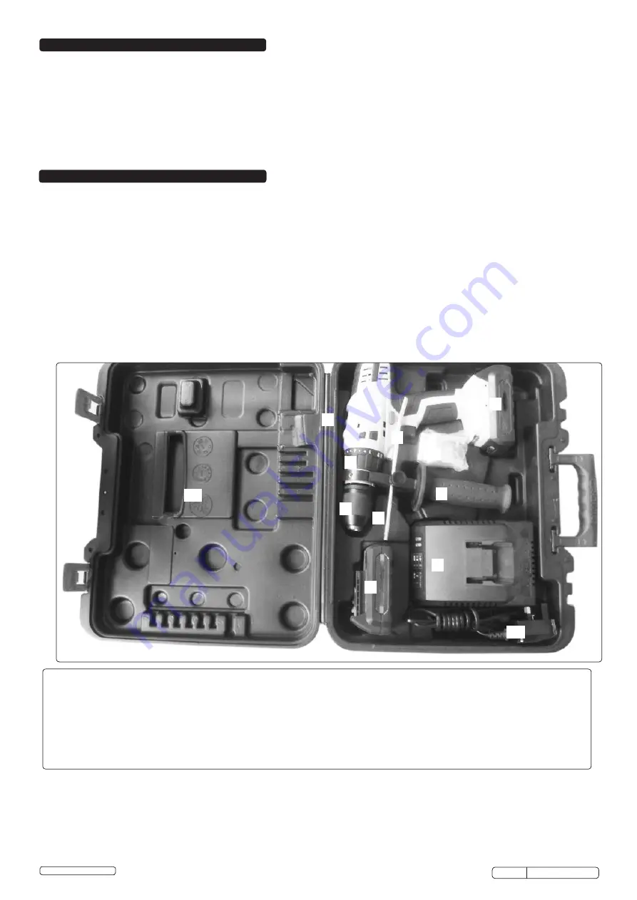
Legend of drill parts-:
1
Keyless Ø13mm chuck
2
Variable speed & torch trigger
3
"HI" and "LOW" speed options
4
Battery (2 supplied)
5
Depth gauge rod
6
Handle
7
Speed and torque setting ring
8
Three position switch cw/locked/acw
9
Mains charger lead and Shuko two pin plug
10
BS Adaptor (for Schuko two pin)
11
Drill clip
12
Carry case
© Jack Sealey Limited
Original Language Version
CP6018V Issue: 2 (I)- 14/01/16


