3.5.
USING THE GENERATOR
WARNING! Do not exceed the wattage capacity of the generator.
3.5.1 Allow the engine to warm up (approximately 3 minutes).
3.5.2 Connect the equipment to the appropriate generator socket.
WARNING!
If connecting to a home power circuit, the unit must be
wired in by a qualified electrician. The incorrect installation of this unit may
cause damage to the generator, the appliance and may lead to the risk of
fire and/or personal injury.
3.6. TO STOP THE GENERATOR
3.6.1 Disconnect the electrical load.
3.6.2 Allow the engine to run unloaded for 1 - 2 mins.
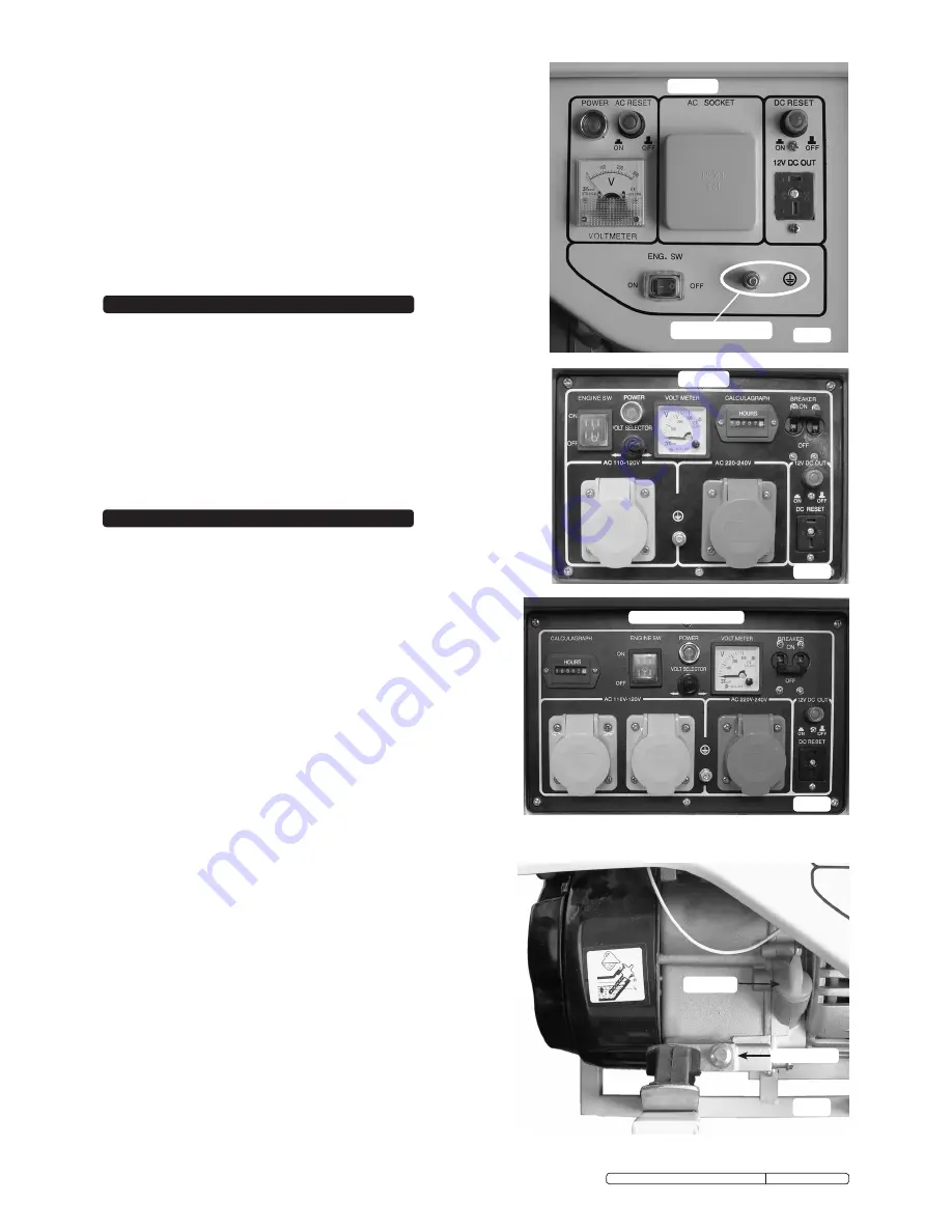
3.6.3 Stop engine by moving the engine switch to the
"OFF"
position, Figs 3 to 5.
3.6.4 Set the circuit breaker to the
"OFF"
position.
3.6.5 Turn off the fuel valve, Fig.1.
Fig.3
Earth Connection
Fig.6
Fig.5
GG1100
GG3800 & GG7500
4. STORAGE & TRANSPORTATION
4.1
Storing the Generator
4.1.1 Always drain off the fuel from the carburettor and fuel tank when storing
the generator for long periods of time.
4.1.2 Drain and refill the engine oil, see Section 5.1.
4.1.3 Store in a dry and childproof area.
4.2
Transporting the Generator
4.2.1 Turn the engine switch and the fuel tap to the
"OFF"
position.
4.2.2 Keep the generator level to avoid fuel spillage and away from sources of
ignition.
4.2.3 Allow the generator to cool before transportation, the engine and exhaust
system can cause serious burns.
Dipstick
Drain Plug
GG2800
Fig.4
Maintenance should be carried out as stated in the maintenance
schedule.
5.1
Changing the Oil
5.1.1 Unscrew the dipstick (Fig.6).
5.1.2 Place a suitable container underneath the drain plug and then
remove the drain plug.
5.1.3 Once the oil has drained replace the drain plug.
5.1.4 Refill with SAE 10W/30 oil.
5.1.5 Replace dipstick.
5.2
Air Filter
5.2.1 Remove screws (GG1100) (Fig.7) or clips on other models and
remove the air filter cover.
5.2.2 Remove the foam element from the air filter assembly (Fig.8).
5.2.3 Wash out the element using paraffin and dry thoroughly.
5.2.4 Dip the element into clean machine oil and remove excess oil.
5.2.5 Ensure air filter housing is clean and replace element and
cover.
Note:
Wear suitable protective gloves when handling element during
cleaning and reproofing.
5.3
Spark Plug
5.3.1 Remove the high tension lead from the spark plug.
5.3.2 Using the supplied spark plug wrench remove the spark plug.
5.3.3 Clean spark plug with a wire brush.
5.3.4 Check the electrode gap with a set of feeler gauges, the gap
should be 0.7mm to 0.8mm (Fig.10).
5.3.5 Check the spark plug washer is in good condition and screw
the plug in by hand to avoid cross threading.
5.3.6 Once the spark plug is installed, tighten it using the spark plug
wrench to compress the washer.
Note:
In the case of a new spark plug being fitted, screw it in by hand
and tighten it by 1/2 turn with a spark plug wrench to compress
the washer. If the spark plug has already been used, screw it in
by hand and only tighten it by 1/8 to 1/4 turn to compress the
washer.
5.4
Carburettor Float Chamber
5.4.1 Turn off the fuel supply switch.
5.4.2 Using a 10mm spanner remove the bolt underneath the float
chamber (Fig.9) and lower the chamber taking care not to spill
any fuel in the process. Dispose of old fuel in line with local
authority regulations and thoroughly clean the chamber.
5.4.3 Replace the O-ring and refit the float chamber.
5.4.4 Turn on fuel supply and check for leaks.
5. MAINTENANCE
Original Language Version
GG1100, GG2800, GG3800, GG7500 Issue: 2 - 12/10/09


