
A health and safety assessment by the user (or employer) will need to be carried out to determine the suitable duration of use for each tool.
nB: stated Vibration emission values are type-test values and are intended to be typical.
Whilst in use, the actual value will vary considerably from and depend on many factors.
such factors include; the operator, the task and the inserted tool or consumable.
nB: ensure that the length of leader hoses is sufficient to allow unrestricted use, as this also helps to reduce vibration.
the state of maintenance of the tool itself is also an important factor, a poorly maintained tool will also increase the risk of Hand Arm
Vibration syndrome.
Health surveillance.
We recommend a programme of health surveillance to detect early symptoms of vibration injury so that management procedures can be
modified accordingly.
Personal protective equipment.
We are not aware of any personal protective equipment (PPe) that provides protection against vibration injury that may result from the
uncontrolled use of this tool. We recommend a sufficient supply of clothing (including gloves) to enable the operator to remain warm and dry
and maintain good blood circulation in fingers etc. Please note that the most effective protection is prevention, please refer to the correct
use and maintenance section in these instructions. Guidance relating to the management of hand arm vibration can be found on the Hsc
website www.hse.gov.uk - Hand-Arm Vibration at Work.
2. intrOductiOn
includes model no. GsA671 and supplied with set of grinding points, chuck spanners and carry-case.
3. SpecificatiOn
model no. .............................................................. GsA67.V2
c
onfiguration
......................................................straight-midi
collet size .......................................................Ø3mm, Ø6mm
free speed ............................................................ 22000rpm
Air consumption............................................................. 7cfm
operating Pressure ....................................................... 90psi
Air inlet size ..............................................................1/4”BsP
length ........................................................................ 165mm
Weight ......................................................................... 0.48kg
noise Power/Pressure ....................................... 104/93dB(A)
Vibration/uncertainty .......................................... 1.1/0.55m/s
2
consumable Parts
model tip Ø tip length length
sA67/W01 mounted Wheel 10mm 25mm 52mm
sA67/W02 mounted Wheel 20mm 20mm 50mm
sA67/W03 mounted Wheel 25mm 22mm 52mm
sA67/W04 mounted Wheel 25mm 10mm 45mm
sA67/W05 mounted Wheel 20mm 26mm 52mm
sA67/W06 mounted Wheel 20mm 25mm 52mm
sA67/W07 mounted Wheel 25mm 25mm 52mm
sA67/W08 mounted Wheel 16mm 26mm 52mm
sA67/W09 mounted Wheel 25mm 25mm 52mm
sA67/W10 mounted Wheel 25mm 25mm 52mm
4. OperatiOn
4.1.
air Supply
Warning!
ensure the air supply is clean and does not exceed 90 psi while operating the die grinder. too high an air pressure and unclean
air will shorten the product life due to excessive wear, and may be dangerous causing damage and/or personal injury.
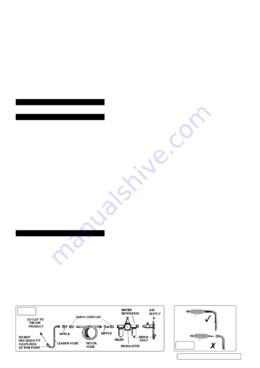
4.1.1. recommended hook-up procedure is shown in fig.1.
ensure die grinder air valve (or trigger) is in “off” position before connecting to the air supply.
4.1.2. You will require an air pressure of 90psi, and an air flow according to specification.
4.1.3. drain the air tank daily. Water in the air line will damage the die grinder.
4.1.4. clean air inlet filter weekly.
4.1.5. line pressure should be increased to compensate for unusually long air hoses (over 8 metres). the minimum hose diameter should be 1/4”
i.d. and fittings must have the same inside dimensions.
4.1.6. Keep hose away from heat, oil and sharp edges. check hose for wear, and make certain that all connections are secure.
4.2.
couplings
.
Vibration may cause failure if a quick change coupling is connected directly to the die grinder. to overcome this, connect a leader hose to
the grinder. A quick change coupling may then be used to connect the leader hose to the air line recoil hose. figs.1 & 2.
fig.1
fig.2
GsA67.V2 | issue 1 16/01/17
Original Language Version
© Jack sealey limited


