
6. air Supply
6.1.
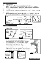
Recommended hook-up fig.2
6.1.1.
Ensure spray gun air valve (or trigger) is in the off position before connecting to the air supply.
6.1.2.
You will require an air pressure of 1.5 to 2 bar (21-30psi), and an air flow according to specification.
WarninG!
Ensure the air supply is clean and does not exceed 2 bar (30psi) while operating the spray gun. Too high an air
pressure and/or unclean air will shorten the product life due to excessive wear, and may be dangerous causing damage and/or
personal injury.
6.1.3.
Drain the air tank daily. Water in the air line will ruin the paint finish and damage the spray gun.
6.1.4.
Clean air inlet filter weekly.
6.1.5.
Line pressure should be increased to compensate for unusually long air hoses (over 8 metres). The minimum hose diameter should
be 1/4” I.D. and fittings must have the same inside dimensions.
6.1.6.
Keep hose away from heat, oil and sharp edges. Check hose for wear, and make certain that all connections are secure.
6.2.
couplinGS
Vibration may cause failure if a quick change coupling is connected directly to the spray gun. To overcome this, connect a leader
hose to the spray gun. A quick change coupling may then be used to connect the leader hose to the air line recoil hose
(fig.2 and 3).
7. operaTion
7.1.
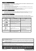
For best results, the gun should be held perpendicular to the surface being sprayed and moved parallel to it. Start the stroke
before squeezing the trigger and release the trigger before finishing the stroke. This will enable accurate control of the
gun and material
(fig.3B).
7.2.
Spray from a distance of about 3.9 to 5.9 inches (100 to 150mm) depending on the material
and the atomizing pressure. The material deposited should always be even and wet. Each
stroke must overlap the preceding stroke to obtain a uniform finish. To reduce over-spray
and obtain maximum efficiency, spray with the lowest possible atomizing air pressure.
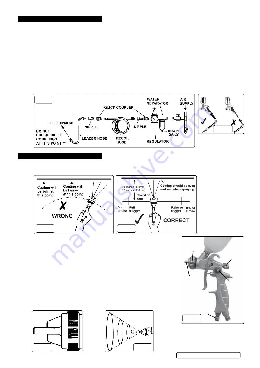
7.3.
Controlling the fan spray and the fluid.
a) Use the needle (paint) adjustment knob (fig.4.2) to adjust the amount of paint flow.
b) The atomizing air flow is controlled by the control knob (fig.4.1).
c) The volume of air input is controlled by the adjustment knob (fig.4.3).
d) As width of spray is increased more material must pass through the gun to obtain the
same coverage on the increased area.
e) Turn the air nozzle (fig.4.4) to achieve a horizontal or vertical fan spray. Lock the nozzle
with retaining ring (fig.4.5). The spray pattern of the gun is variable from round to flat with all
patterns in between. In normal operation, the wings on the nozzle are horizontal (fig.5). This
provides a vertical fan-shaped pattern which gives maximum, uniform and even coverage
when moving the gun back and forth, parallel to the work surface (fig.6).
fig.2
fig.3
fig.3A
fig.3B
1
2
3
4
5
fig.4
fig.6
fig.5
HVLP04 Issue 1 11/01/19
Original Language Version
© Jack Sealey limited


