background image

3.  SPECIFICATION

Capacity ..........................................................................454kg

Min. height .....................................................................190mm

Max. height ....................................................................710mm

Width .............................................................................690mm

Length .................................................(platform only) 2200mm

Overall length ........................................... (inc. ramp) 2860mm
Air supply ................................................Min 100psi/Max 120si 

OPE

RATION

Air supply ..................................................................... 1/4”BSP
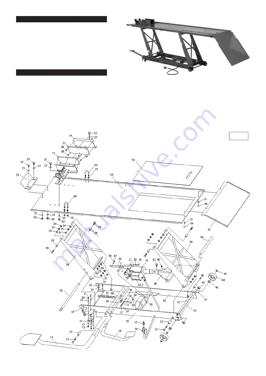
4.  ASSEMBLY


Unpack the lift and check contents with list below. Should there be any damaged or missing parts, contact your supplier immediately.


NOTE! All numbers refer to fig.1.

 Contents


·Main Assembly       ·Sliding Plate             

·Loading Plate        ·Vice


·Lift Foot Pedal        ·Release Foot Pedal    ·Locking Bar        ·Bolts, Washers, Nuts, Cotter-Pins.

4.1.    

Place the sliding plate (36) on the platform (35) to cover the rear wheel removal aperture. 

4.2.    

Attach loading plate (37) to end of platform using washers (23) and Cotter-pins (04).

4.3.    

Fit the front wheel vice assembly (34) to the front of the platform using bolts (33), washers (23) and nuts (30).

4.4.    

Fit the baffle plate (32) using bolts (33), washers (23) and nuts (30).

4.5.    

Fit the lift foot pedal (11) to the pump piston spindle (09) and fit the release foot pedal (10) to the release valve spindle(05).

   fig.1

MC401A  Issue:3 (HFS) - 02/10/18

Original Language Version

© Jack Sealey Limited

Summary of Contents for MC401A

Page 1: ...ve ill fitting clothing Remove ties watches rings and other loose jewellry and contain long hair 9 9 Keep proper balance and footing do not overreach and wear nonslip footwear 9 9 Only use this lift on a surface that is stable level dry and capable of sustaining the load 9 9 Ensure the motorcycle is adequately secured to the lifting platform with appropriate straps 9 9 When the platform has been r...

Page 2: ...ft Foot Pedal Release Foot Pedal Locking Bar Bolts Washers Nuts Cotter Pins 4 1 Place the sliding plate 36 on the platform 35 to cover the rear wheel removal aperture 4 2 Attach loading plate 37 to end of platform using washers 23 and Cotter pins 04 4 3 Fit the front wheel vice assembly 34 to the front of the platform using bolts 33 washers 23 and nuts 30 4 4 Fit the baffle plate 32 using bolts 33...

Page 3: ...he lift foot pedal 11 to raise the lift 6 9 When the platform has been raised to the working height turn off the air valve or stop pumping and pass the locking bar 22 through the holes in the front lifting arm 38 so that the lift cannot be lowered inadvertently 6 10 When work is done check under the lift to ensure that there are no obstructions and that it is safe to lower the unit Remove the lock...

Page 4: ...No Liability is accepted for incorrect use of this product Warranty Guarantee is 12 months from purchase date proof of which is required for any claim ENVIRONMENT PROTECTION Recycle unwanted materials instead of disposing of them as waste All tools accessories and packaging should be sorted taken to a recycling centre and disposed of in a manner which is compatible with the environment When the pr...

Reviews: