


5. AIR SUPPLY
5.1.
You will require an air pressure of minimum 100psi, maximum 120psi
to get the best performance from this lift.
WARNING!
Ensure the air supply does not exceed 120psi while operating the lift. Too high an air pressure and unclean air will shorten
the product’s life due to excessive wear, and may be dangerous, causing possible damage and/or personal injury.
5.2.
Drain the air tank daily. Water in the air line will damage the lift.
5.3.
Clean the air inlet filter screen weekly.
5.4.
Keep the air hose between the compressor and the lift as short as possible, and install an air filter and oiler.
5.5.
Line pressure should be increased to compensate for unusually long air hoses (over 8 metres). The minimum hose diameter should be
1/4” I.D. and fittings must have the same inside dimensions.
5.6.
Keep hose away from heat, oil and sharp edges. Check hoses for wear, and make certain that all connections are secure.
6. OPERATION
6.1.
Leave the pump for one hour to allow the oil to settle before purging the system.
NOTE!
Failure to allow sufficient air supply hose quick coupler-female and fully press the release foot pedal (10), then turn on the
air valve letting the pump work for 20 seconds to eliminate any air in the hydraulic system.
6.2.
Test the lift, unladen, by raising it to full height and then lowering it. Depress release foot pedal (10) slowly to control the rate of descent.
WARNING!
Ensure that you read, understand and apply the safety instructions and warnings before use.
WARNING!
Do not attempt to overload the lift.
6.3.
Position the lift in a suitable area, checking that the surface on which the lift will stand is solid and flat (preferably concrete).
6.4.
Turn the adjusting screw assy (18) down to raise the castors off the ground to prevent the lift from moving.
6.5.
Wheel the motorcycle up the loading plate and onto the platform.
NOTE:
There is a choice of mounting holes for the vice to cater for various sizes of motorcycle.
6.6.
Clamp front wheel in vice to prevent any movement of the motorcycle.
6.7.
Strap the motorcycle securely to the platform.
6.8.
Connect the quick coupler-male into the air supply hose quick coupler-female, then turn on the air valve to raise the lift. When air source
is not available, pump the lift foot pedal (11) to raise the lift.
6.9.
When the platform has been raised to the working height, turn off the air valve (or stop pumping) and pass the locking bar (22) through
the holes in the front lifting arm (38) so that the lift cannot be lowered inadvertently.
6.10.
When work is done, check under the lift to ensure that there are no obstructions and that it is safe to lower the unit. Remove the locking
bar and then SLOWLY press the release foot pedal to GENTLY lower the lift.
NOTE!
The speed of lowering is controlled by the release valve. The more the valve is opened the more rapidly the lift descends. Ensure
the decent is slow and controlled.
6.11.
When the lift is fully lowered, unstrap the motorcycle, open the vice jaws and remove the cycle from the lift.
7. MAINTENANCE
7.1.
Clean and lubricate on a regular basis.
7.2.
Regularly check oil level via filler hole. With piston fully down remove filler plug, oil should be level with bottom of filler hole. Top-up as
necessary. Use a good quality jack oil such as Sealey Hydraulic Jack Oil. Do not use brake fluid.
Ensure no dirt enters hydraulic system when filling or removing/replacing components.
7.3.
Always dispose of waste oil according to local authority guidelines. If in doubt consult your local authority.
7.4.
Keep the lift clean and wipe off any oil or grease. Lubricate all moving parts.
7.5.
Before each use check all parts. If any part of the lift is damaged or suspect, remove the lift from service and take necessary action to
repair.
IMPORTANT:
NO RESPONSIBILITY IS ACCEPTED FOR INCORRECT USE OF THIS PRODUCT.
Hydraulic products are only repaired by local service agents. We have service/repair agents in all parts of the UK.
DO NOT RETURN PRODUCT TO US
. Please telephone us on 01284 757500 to obtain the address and phone number of your local
agent. If product is under guarantee please contact your dealer.
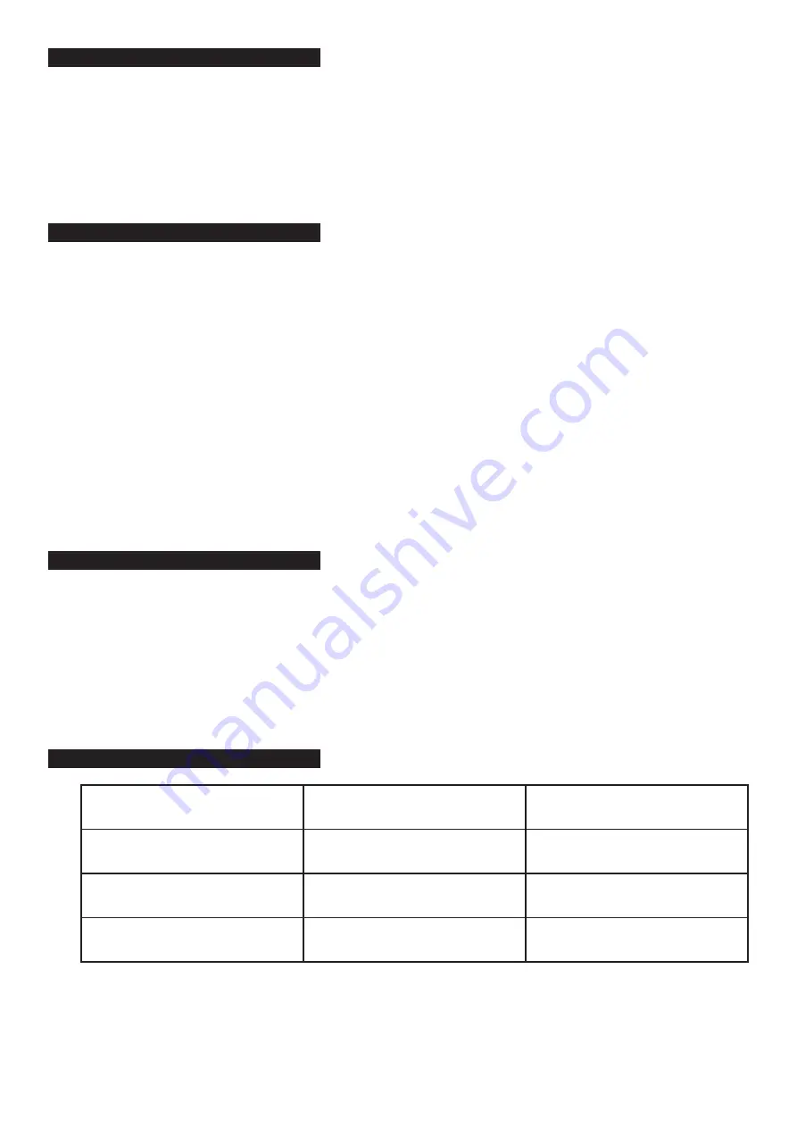
8. TROUBLESHOOTING
Lift will not lift load.
1. Release valve not fully closed.
2. Oil level low.
3. Air supply low.
1. Close valve firmly.
2. Top-up to correct level.
3. Min. requirement 120psi.
Lift will not hold load.
1. Release valve not fully closed.
1. Close valve firmly.
Lift will not lift smoothly
or to full height.
1. Oil level low.
2. Air in hydraulic system.
1. Top-up to correct level.
2. Bleed system.
Lift will not lower completely.
1. Release valve not sufficiently open.
1. Slowly open valve further.
MC401A Issue:3 (HFS) - 02/10/18
Original Language Version
© Jack Sealey Limited


