4. ASSEMBLY
4.1.
Check parts against parts diagram before assembly.
4.2.
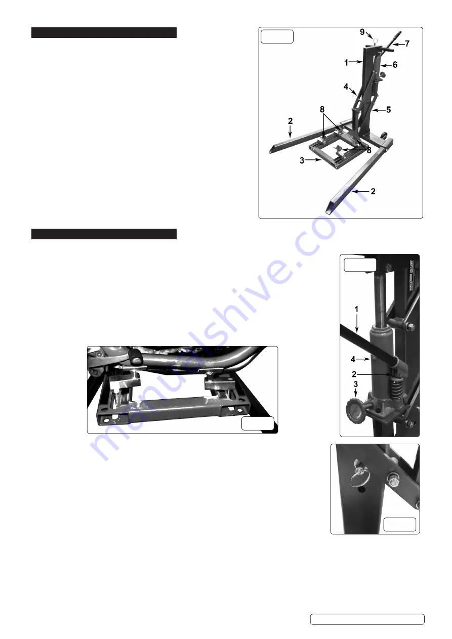
Locate the legs (fig.1.2) into the body assembly (fig.1.1) and secure
using M12 bolts, nuts and washers.
4.3.
Secure the cradle assembly (fig.1.3) to the upper (fig 1.4) and
lower parallel arms (fig.1.5) using pins and M12 nuts and washers.
4.4.
Secure the head of the hydraulic unit (fig.1.6) to the body
assembly (fig.1.1) using an M12 bolt, nut and washers.
4.5.
The foot of the hydraulic unit is secured using 2 x M8 internal hex
bolts with nuts and washers.
4.6.
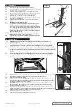
Locate the pumping handle (fig.1.7/2.1) into the pump socket
(fig.2.2).
4.7.
BLEEDING THE HYDRAULIC UNIT
4.7.1.
The hydraulic unit will require bleeding before use owing to the
oil being disturbed during transport. Open the release valve
(fig.2.3) slightly and pump about 20 strokes with the pump handle
(2.1). Close the valve and top-up the reservoir with a good quality
jack oil HJO500HLS, HJO5LS (
NOT
brake fluid). To do this,
remove the reservoir cap (fig.2.4) and fill to just below the level of
the entry. Replace the cap.
4.7.2.
The action of the jack should now be firm, all air having been
expelled from the system. If not, repeat step 4.6.1.
4.8.
When not in use, the locking pin should be kept safe by placing it
in the top of the body assembly as in fig.1.9.
5. OPERATION
WARNING!
Ensure that you read, understand and apply the safety instructions before use.
WARNING! DO NOT
attempt to overload the lift.
5.1.
Position the lift in a suitable area, checking that the surface on which the lift will stand is solid and flat
(preferably concrete).To move the lift, pull back until the wheels are in contact with the ground.
5.2.
The lift may be used either with or without the frame supports (fig.1.8) in place. If desired, drop the
threaded stems through the slots in the cradle frame and secure the stands in the correct position with
an M16 nut. A second nut may be fitted to the stem above the frame to alter the relative height of the
stands.
8
DO NOT
attempt to lift a motorcycle without securing to the cradle with suitable ratchet straps.
5.3.
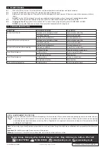
Position the cradle beneath the motorcycle and adjust the position of the frame supports beneath
suitable parts of the frame, taking care not to damage any exhaust components, pipes or cables.
(see fig.3).
5.4.
TO LIFT
: Close the release valve fully and use the pump handle to raise the cradle into light contact
with the motorcycle frame. Tighten the nuts on the frame support stems to lock.
5.5.
Secure the load with ratchet straps.
5.6.
Pump up to a convenient height;
DO NOT
leave the load supported by the hydraulic unit alone;
insert the locking pin into the hole below the lower arm and lower the arm gently onto the pin (fig.4)
by opening the release valve (fig.2.3) gradually.
5.7.
TO LOWER:
Before lowering, ensure that the area below the cradle is clear and that everyone
stands well clear of the mechanism. Close the release valve and pump the cradle clear of the
locking pin. Remove the locking pin.
5.7.1.
Open the release valve gradually to allow the cradle to descend gently. When the motorcycle is
bearing its own weight, close the release valve and remove the strapping; when removed, open the
release valve again to allow the cradle to settle at its minimum height.
5.8.
Withdraw the lift from beneath the motorcycle.
5.9.
Store in a safe, dry, child proof location when not in use.
fig.1
fig.2
fig.3
fig.4
MCL500 Issue 2 (H2F) 24/04/20
Original Language Version
© Jack Sealey Limited


