background image

4.7.    

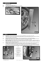
Attaching the scale units to the front wheel:

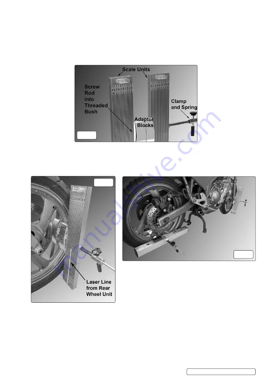
 Referring to fig.5, loosen the clamp and remove the clamp unit and spring from the  


rod together with the right hand scale unit. Position the left hand scale unit with the rod attached on the nearside of the front wheel  


in a near vertical orientation and insert the rod through the adaptor and then through the front part of the wheel. Slide the right hand  


adaptor and scale unit onto the rod and up to the tyre, followed by the spring and clamp the two units lightly to the wheel using the  


adaptors on the wheel rim to space the laser unit away from the tyre in the position indicated in fig.6.

4.8.    

Switch on the lasers and note the position of each beam on the scales. If necessary, adjust the position/angle of the laser units on  


the rear wheel to get the beams to appear on the scales.

4.9.    

Front wheel position: The front wheel must be in the straight ahead position before accurate alignment can take place. If the beams  


are parallel with the scale lines the front wheel is set dead ahead. If the beams are at an angle to the scale lines, turn the wheel    


one way or the other until they are parallel.

4.10. 

AlignMent ProceDure

4.11.   

Compare the readings on the scales. If they are the same then the rear wheel is in alignment with the front wheel. If they are not   


the same then it will be necessary to operate the rear wheel adjusters. If the reading is higher on the right hand scale, tighten the   


left hand adjuster. If the reading is higher on the left hand scale, tighten the right hand adjuster. When the wheels are in alignment,  


finally tighten the rear wheel axle fixings.

   fig.5

   fig.6

   fig.7

MS070.V2 Issue 2 (H4F) 25/05/18

Original Language Version

© Jack Sealey limited

Summary of Contents for MS070.V2

Page 1: ...ch cannot be built into this product but must be applied by the operator 9 9 Any alignment changes deemed necessary as a result of using this equipment must be made strictly in accordance with the motorcycle manufacturer s recommendations Laser Safety The MS070 utilises a Class 2M laser that emits low levels of visible radiation light i e wavelengths between 630 and 640 nanometres which are safe f...

Page 2: ...ts you must ensure that the motorcycle is adequately supported on a suitable stand that lifts the rear wheel from the ground and supports the motorcycle in a perpendicular orientation The stand must also be on a firm stable surface such as concrete 4 6 Attaching the laser units to the rear wheel Referring to fig 3 loosen the clamp and remove the clamp unit and spring from the rod together with the...

Page 3: ...le of the laser units on the rear wheel to get the beams to appear on the scales 4 9 Front wheel position The front wheel must be in the straight ahead position before accurate alignment can take place If the beams are parallel with the scale lines the front wheel is set dead ahead If the beams are at an angle to the scale lines turn the wheel one way or the other until they are parallel 4 10 Alig...

Page 4: ...n compliance with the EU Directive on Waste Electrical and Electronic Equipment WEEE When the product is no longer required it must be disposed of in an environmentally protective way Contact your local solid waste authority for recycling information Battery Removal see section 4 Under the Waste Batteries and Accumulators Regulations 2009 Jack Sealey Ltd are required to inform potential purchasers...

Reviews: