4.1.
WELDING CABLE “ELECTRODE HOLDER” CONNECTION
4.1.1.
Before connecting cables it is important to refer to the electrode manufacturer’s instructions on the electrode packaging which will
indicate the correct polarity connection for the electrode, together with the most suitable current to use.
4.2.
ARC WELDING
4.2.1.
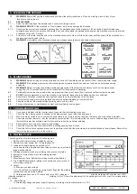
In principle, when ARC welding the Electrode Holder ”POSITIVE” is normally connected to the “POSITIVE” (+) terminal (fig.1).
4.2.2. The WORK CLAMP cable is connected to the terminal not occupied by the electrode holder cable. The clamp is connected to:
a) The work piece, or
b) A metallic work bench. The connection must be as close to the proposed weld as possible.
WARNING!
Cable connectors must be turned into the quick plugs fully to ensure a good electrical contact. Loose connections will
cause overheating, rapid deterioration and loss in efficiency.
8
DO NOT
use welding cables over 10m in length.
With the exception of a metallic workbench
DO NOT
connect the return cable to any metallic structure which is not part of
the workpiece, as this will jeopardise weld quality and may be dangerous.
4.3.
BACK PANEL (FIG.1)
Rocker switch. Turns mains power on and off.
4.4.
FRONT PANEL (FIG.2)
4.4.1.
Welding Current Control:
Regulates welding current.
The set value will be displayed in the display panel.
4.4.2.
Power Indicator:
Illuminates when machine is
switched on ready for use.
4.4.3.
Alarm Indicator:
Illuminates when the circuitry within the machine overheats. Allowing the inverter to cool down naturally will
restore operation after a period of time. See rating plate for details of duty cycle.
4.4.4.
VRD
Indicator illuminates when the voltage reduction device is active. To operate the VRD, press the function button and hold for 2
seconds. The display will read ‘VRD’ and by turning the Welding Current control dial it can be turned ‘On’ or ‘Off’.
4.4.5.
Hot Start
function is a feature that pumps up the amperage for a short time when you start the arc. Higher amperage helps
to start the arc easier without sticking the electrode to the base metal. To enable this feature, press the function button and hold for
2 seconds and VRD is displayed. Press the function button once more to engage this feature. Rotate the knob left to adjust to -10
or right to adjust to +10
4.4.6.
Lift TIG Indicator:
With Lift-Arc Ignition feature, to start the arc the tungsten electode is touched on the job and lifted off. The start-
up current is very low and therefore the tungsten barely sticks to the job and the sharpened point is not damaged. The tungsten
is then easily lifted off the job. The machine senses that the contact is broken and begins supplying full welding current. To enable
this feature, press the function button and hold for 2 seconds, VRD will be displayed. Press the function button once more to
display HS and press the downward arrow one more time to engage the Lift TIG function. Press the button again in order to exit the
menu system.
4.5.
ELECTRODES
The welding current must be regulated according to the diameter of the electrode in use and the type of joint to be welded. See
diameter/current chart below.
Fig. 1
Fig. 2
Original Language Version
© Jack Sealey Limited
MW180i, MW200i Issue:1 24/11/21
VRD Indicator
Alarm Indicator
Power Indicator
Hot Start
Lift TIG
Indicator
Function
Selector
Welding
Current
Control
Electrode Ø
mm
Minimum Welding Current Amps
Maximum Welding Current Amps
1.6
25
50
2.0
40
80
2.5
60
110
3.2
80
160
4.0
120
200


