6. CABLE CONNECTION
WARNING!
Ensure that the inverter is not plugged into the mains power supply
before assembling, connecting or disconnecting cables. For electrical installation,
see Safety Instructions (Section 1).
WARNING!
Failure to follow the electrical safety instructions may affect the
operating performance and could damage the built-in safety system which, in
turn, could result in personal injury or fatality and will invalidate the warranty.
6.1.
WELDING CABLE “ELECTRODE HOLDER” CONNECTION
Before connecting cables it is important to refer to the electrode manufacturer’s
instructions on the electrode packaging which will indicate the correct polarity connection
for the electrode, together with the most suitable current to use.
6.1.1. ARC WeldING
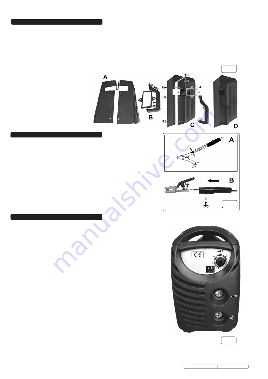
In principle, when ARC welding the electrode Holder ”PosITIVe” is normally
connected to the “PosITIVe” (+) terminal (fig. 5).
6.2.
WELDING “RETURN CABLE” - (WORK CLAMP) CONNECTION
The WoRK ClAMP cable is connected to the terminal not occupied by the electrode
holder cable.
The clamp is connected to:
a) The workpiece, or
b) A metallic work bench. The connection must be as close to the proposed weld as
possible.
WARNING!
Cable connectors must be turned fully into the quick plugs to ensure a
good electrical contact. Loose connections will cause overheating, rapid
deterioration and loss in efficiency. DO NOT use welding cables over 10m in length.
With the exception of a metallic workbench DO NOT connect the return cable to
any metallic structure which is not part of the workpiece, as this will jeopardise
weld quality and may be dangerous.
5. CABLE CLAMP ASSEMBLY
5.1.
Work Clamp
(see fig.4-A)
5.1.1. Remove the black rubber sleeve from the clamp arm which has the screw and
plate and thread the cable through the rubber sleeve. Remove the pre-cut
section of insulation from the cable end.
5.1.2. loosen the clamp screw and plate and lay the cable into the back of the
arm with the bare wire under the plate. Tighten the clamp screw.
5.1.3. slide the black rubber sleeve back over the clamp arm.
5.2.
Electrode Holder
(see fig.4-B)
5.2.1. Undo the handle retaining screw . Pull the handle from the head and thread the
free end of the cable through it, as shown. Remove the pre-cut section of
insulation from the cable end.
5.2.2. loosen the clamp screw on the handle and fit the bared cable core under the
clamp plate as shown.
5.2.3. Tighten screw to clamp the cable end.
5.2.4. Refit the handle to the head and insert the retaining screw.
4. WELDING MASK ASSEMBLY
MW80, MW125, MW155 Issue No.1 04/05/10
Original Language Version
4.1. Assembly
: Referring to fig.3, separate the main components of the mask as shown in A and B into their separate parts. Trim
any spikes and burrs of excess plastic from the pieces in preparation for assembly.
4.1.1. overlap the two main halves of the mask so that the fixing holes line up and insert one fixing (1) from the outside into the hole
above the window. Place the assembly face downwards.
4.1.2. lay the tinted glass window (2) over the window opening and lay the frame (3) over the glass. screw a plastic retainer ring (4)
onto fixing (1).
4.1.3. lift up the assembly and insert the handle threads (7) through the two holes below the window. Turn the assembly over and fix
the handle with plastic retaining rings 8 and 9.
4.1.4. Insert fixing (5) through the remaining hole in the top of the mask and fix it with the remaining retaining ring (6).
4.2. Use
: Always hold mask close to the face to provide maximum protection from radiation and droplets of molten metal.
4.2.1. Before each use check that the mask is
undamaged and that the filter glass is in
position and firmly retained. Remove any
metal droplets that may be on the glass.
Danger! Never use a filter glass that is
chipped, cracked or otherwise faulty
as severe eye damage may result.
Warning! Do not allow the mask to
come into contact with flame as the
fumes produced are harmful.
4.2.3. Clean with soapy water, do not use
solvents.
fig.3
fig.4
fig.5
MW125, MW155


