


5. ASSEMBLy
5.1.
MANuAL OPERATION (Refer to Fittings List section 4)
5.1.1.
Use Contents C and handle m to raise and lower.
5.2.
ELECTRIC OPERATION
WARNING!
DO NOT
use air tools.
5.2.1.
Fit F electric drill drive housing. Refer to fig.A for fixings.
5.3.
WIDTH ADJuSTMENT
To adjust the width of the lift refer to the Width 1, 2 & 3 diagrams in
Section 4 Contents
5.3.1.
Remove the side cover, C section cover (this protects the drive shaft).
5.3.2.
Undo the screws on K (this holds the two halves of the drive shaft together).
5.3.3. Undo the four sets of nuts and screws that hold the two halves of the car lift together.
5.3.4.
Refer to the vehicle to be lifted and select the correct extension pieces
(either Width 2 or 3).
NOTE:
It may be necessary to use a rubber mallet to separate the two halves
of the lift.
5.3.5.
Fit the extension pieces, using the extra sets of screws supplied.
5.3.6.
Fit the drive shaft extension piece and remember to fit the rubber block part L and secure through part Q or V using self tapping
screws J.
5.3.7.
Check that all fixings are secure.
6. OPERATION
6.1.
GENERAL CONSIDERATIONS
6.1.1.
Use on a flat, hard, smooth floor (for example, concrete). A rough floor can hinder the working of the mini lift, by putting up too much
resistance to the movement of the castors.
6.1.2.
Before lifting or lowering the load, systematically check that the obstacles preventing the descent (jack stands and anti-tilt arm) are
removed.
6.1.3.
Load Limitation
6.1.3.1. The connecting pin B (Section 4 Contents) between the drill and the mini lift acts as a protection in the event of excessive load or when
the maximum height is reached.
6.1.3.2. In these situations, the breaking of this pin is normal. Replace this pin with a genuine new pin, then continue using, making sure that the
instructions for maximum load and height are followed.
8
DO NOT
use the mini lift with a pin different to the one originally supplied.
6.1.4.
The load limiting pin is going to break if the user overrides the stops by continuing to operate the drill.
6.1.4.1. The mini lift is fitted with end stops, for the maximum lift position and the lowest position. Before reaching the end of the lift, it is
therefore necessary To GRAdUAllY SloW the movement and to stop it before reaching the stop.
6.1.5.
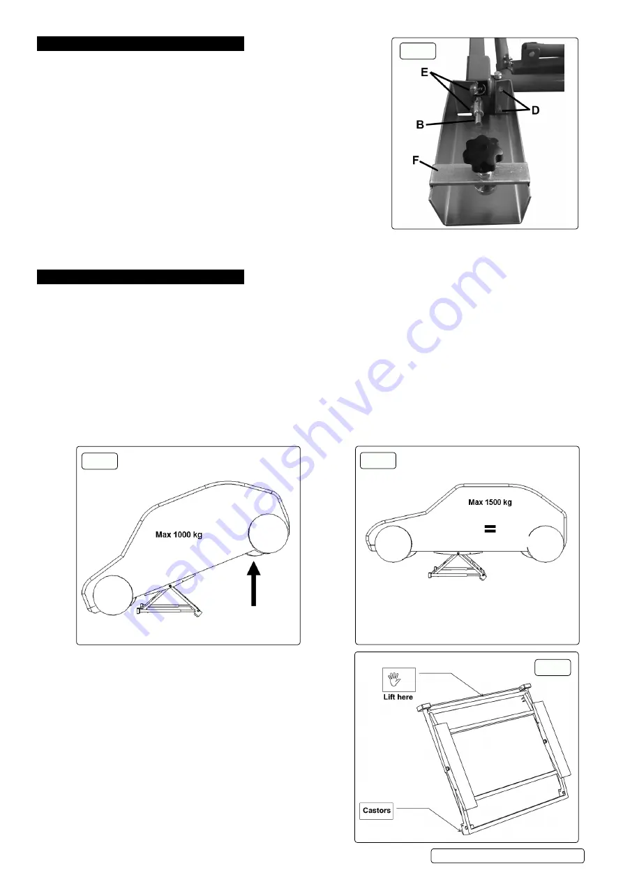
Lifting
refer to fig’s 1 & 2
6.1.5.1.
When lifting the vehicle,
DO NOT
try to raise the 4 wheels
simultaneously, but let it rest freely on the front or rear wheels.
6.1.5.2. The maximum lifting capacity is 1000 kg, which means you can lift
heavier vehicles when 2 wheels are resting on the ground.
6.1.5.3. once the vehicle is lifted, the maximum static capacity is 1500 kg. This
means the vehicle can be placed horizontally with the four wheels lifted
(if it does not exceed 1500 kg).
6.1.6.
Moving refer to fig.3
WARNING!
The mini lift is heavy.
DO NOT
try to lift it yourself.
6.1.6.1. Take hold of the mini lift between the two drive housings and move it
by rolling it on the castors located on the other side.
fig.2
fig.1
fig.3
Original Language Version
© Jack Sealey limited
PPl01 | Issue 3 (4) 18/11/19
fig.A


