6.2.
OPERATION
6.2.1.
The vehicle must have the hand brake off and be in neutral. It must be on a horizontal surface so that it does not roll because of its own
weight.
6.2.2.
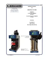
Place the mini lift at the side of the vehicle. The drive housings must be placed towards the front of the vehicle.
6.2.3.
Slide the mini lift under the vehicle, until it is centred with the longitudinal axis of the vehicle. Adjust the distance between the runners
to fit the width of the vehicle.
6.2.4.
The two rubberised runners must be symmetrical in relation to the bottom of the car body. Check the manufacturer’s manual to ensure
that the runners are not in contact with any fragile component of the vehicle.
6.2.5.
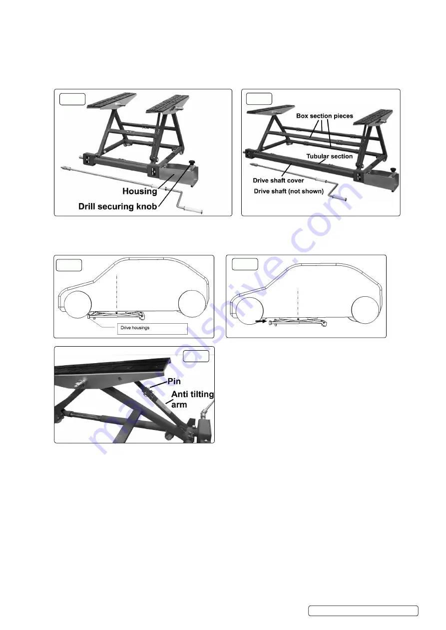
To lift the front of the vehicle refer to fig.6
6.2.5.1.
Place the drive housings in contact with the front wheels of the vehicle (for front-engine vehicles).
6.2.6.
To lift the rear of the vehicle refer to fig.7
6.2.6.1.
move the mini lift back slightly so that most of the weight is transferred onto the front.
6.2.7.
Lifting (Electric Operation)
6.2.7.1.
Insert the connecting pin ( Section 4 Contents B) in the drill chuck. The cardan supplied is only for lifting with the crank.
6.2.7.2. Place the drill in the housing, inserting the connecting pin in the control shaft in the housing. Tighten the drill with the knob on the housing.
6.2.7.3. operate the drill (direction of rotation to the right) holding it firmly.
6.2.7.4. Before reaching the maximum height, slow the lifting speed.
6.2.7.5.
Insert the pin in the anti-tilting arm, refer to fig.8 .
WARNING!
Check that the vehicle is stable before working underneath it. It must not be able to slip or tilt, even if the user should push
against it while working. If there is a risk of the vehicle tilting, re-lower the mini lift and move it so as to place more weight on the wheels
which remain on the ground.
WARNING! Install a pair axle stands before working under the vehicle.
note: It is also possible to lift or lower the load using the crank and the cardan supplied.
6.2.8.
Lowering
6.2.8.1.
Remove the axle stands.
6.2.8.2. Remove the pin from the anti-tilt arm locking mechanism. If you forget to loosen this mechanism, it can lead to damage to the mini lift.
6.2.8.3. operate the mini lift using the drill (or the crank), changing the direction of rotation.
6.2.8.4. lower the mini lift until the load is no longer resting on it and it can easily be removed from the side.
6.2.8.5. Before reaching the minimum height, gradually slow the lowering speed.
6.2.9.
Tilting
WARNING!
only for working on the front or the rear of the vehicle.
fig.5
fig.4
fig.6
fig.6
fig.7
fig.8
Original Language Version
© Jack Sealey limited
PPl01 | Issue 3 (4) 18/11/19
fig.6