3.3.
assembling loose parts/accessories.
3.3.1. screw the head lever into position (make secure, but do not overtighten).
3.3.2. fit the bar holding rod - see parts diagram, item 43 (sM3154) item 10 (sM2504).
3.3.3. fix the pedestal firmly onto the base.
3.4.
Fitting/replacing a blade.
DANGER! The use of damaged blades is dangerous and may cause personal injury.
WARNING! Ensure the saw is isolated from the mains power supply before attempting to
change the blade.
Before using a saw blade check that it is undamaged, undistorted and the teeth are sharp.
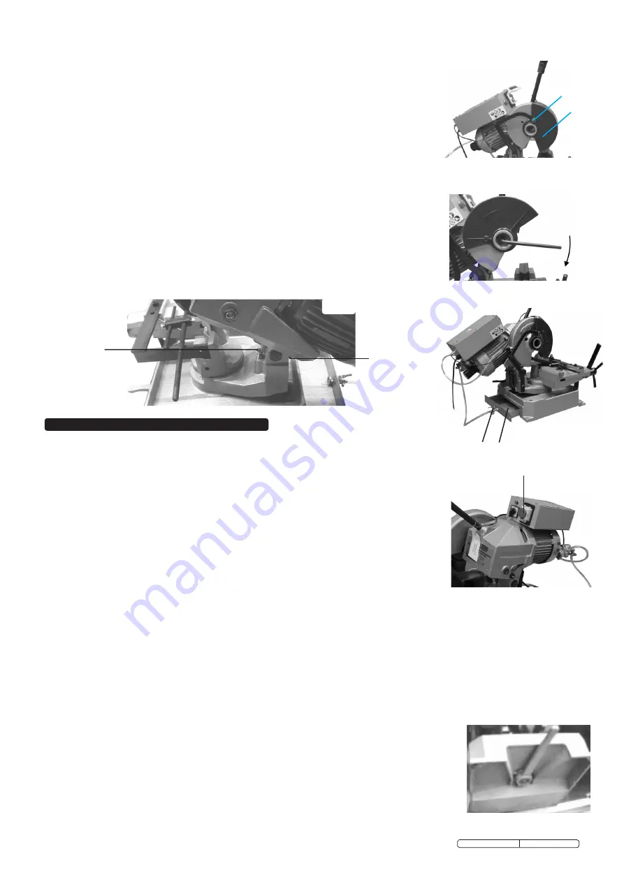
3.4.1. release the mobile guard and turn it back (fig.3).
3.4.2. Grip a block of wood in the vice and lower the old/damaged blade (if present) on it.
3.4.3. Insert the key provided and remove the screw (fig 4) by turning in a clockwise direction
(it has a left-handed thread) then slip off the flange that holds the blade.
3.4.4. fit the new blade, being sure to check the cutting direction of the teeth, then replace the flange,
the screw and the mobile guard.
3.5.
fill coolant tank (fig 5A). confirm tap (fig 5B) is open.
3.6.
check sight-glass and visually confirm that there is oil in the gearbox (fig 11c).
3.7.
Pull control lever forward as far as possible, to lower blade, and confirm that blade is clear of saw
base in this position. If blade is touching base then adjust abutment screw (fig 6A) to achieve
clearance. note: fig.6 shows typical abutment screw location which vary slightly between models.
3.8.
raise blade as far as possible and confirm that rear of motor is clear of base. If motor is touching
base then adjust abutment screw (fig 6B) to achieve clearance.
3.9.
confirm all tools have been removed from saw, main switch is ‘off’ and blade guard is in position.
4. OPeRatING INStRUCtIONS
WaRNING!
Before using saw ensure you wear approved safety goggles, ear defenders,
appropriate dust mask if saw generates dust and safety gloves, and that all other safety
instructions in chapter 1 are followed carefully. Do not operate the saw if you suspect any
part of it is overly worn, damaged or malfunctioning in any way.
4.1.
Securing workpiece.
4.1.1. Ensure the saw is switched off at the main switch and then secure workpiece in the base vice,
tightening via the handwheel. We recommend that you place a block of wood (slightly narrower than
the work piece) in the vice below the item to be cut to act as a support.
4.1.2. When cutting a long workpiece use additional supports along the length.
4.2.
the ‘On’ and ‘Off’ switch.
With saw connected to mains power supply, ensure that the machine is not in emergency stop
condition and if it is, release the emergency stop button (fig 7A) by pushing the red button
upwards and releasing the catch. select speed (model 3145 only) and start saw by depressing
the button located in the handle of the head control arm. check to ensure that sufficient
coolant/lubricant is being delivered. release the handle button to stop saw during normal
operation. If malfunction occurs/appears imminent, press the red emergency stop button to halt
machine operation immediately.
fig 3
4.3.
Operating.
WaRNING!
DO NOT switch the saw on whilst the blade is in contact with the workpiece. Bring the rotating blade to the workpiece.
4.3.1. the blade must be running at maximum speed and coolant flowing before attempting to lower the cutting edge onto workpiece.
4.3.2. Lower the blade slowly and smoothly towards the workpiece (avoid jerky movements).
4.3.3.
Exert adequate downward pressure on the handle to allow cutting according to the type and size of the material you are working with.
Avoid subjecting the blade to excessive strain, always ease the blade down against workpiece (a harsh downward impact may break
the blade or damage the teeth).
Do not apply undue force on the handle in order to cut workpiece. Maintain a controlled cutting speed through the workpiece.
4.3.4. When starting to cut with a new blade, the first 2-3 cuts must be made exerting only slight pressure on the handle, so that the time
taken to complete the cut is approximately double that taken during normal operation.
4.4.
Completing the cut.
4.4.1. When cutting is completed, carefully raise the blade to its full extent.
4.4.2. release the button and wait until the blade has fully stopped before attempting to remove the workpiece.
4.5.
Mitre cutting.
to cut the workpiece at an angle the saw head must be adjusted.
4.5.1. sM2504 - to effect an angled cut, turn the locking lever to the left (fig 8) and rotate
the saw/motor assembly to the required angle, reading the graduated scale, up to a maximum of ±45°.
4.5.2. fix the saw/motor assembly in position by turning the locking lever firmly to the right.
4.5.3. sM3154 - to effect an angled cut, move the locking lever to the left and rotate the saw/motor
assembly to the required angle, reading the graduated scale, up to a maximum of ±45° in either direction.
4.5.4. fix the saw/motor assembly in position by sliding the revolving locking lever firmly to the right.
fig 4
unscrew here
turn back
guard
fig 5
B
A
fig 6
A
B
A
fig 7
fig 8
Original Language Version
sM2504, sM3154 Issue: 4 - 07/01/10


