5. MaINteNaNCe
WaRNING!
Ensure the saw is isolated from the mains power
supply before attempting any maintenance.
5.1.
daily maintenance.
5.1.1. General cleaning of the saw to remove accumulated shavings/filings.
5.1.2. top up the level of lubricating coolant in the coolant tank (fig 5).
5.1.3. check the blade for wear.
5.1.4. Lift the head to a high position to avoid stress on the return spring.
5.1.5. check the guards and emergency stop for signs of wear/malfunction.
5.2.
Weekly maintenance.
5.2.1. More thorough cleaning of the saw to remove accumulated
shavings, especially from the lubricant fluid tank.
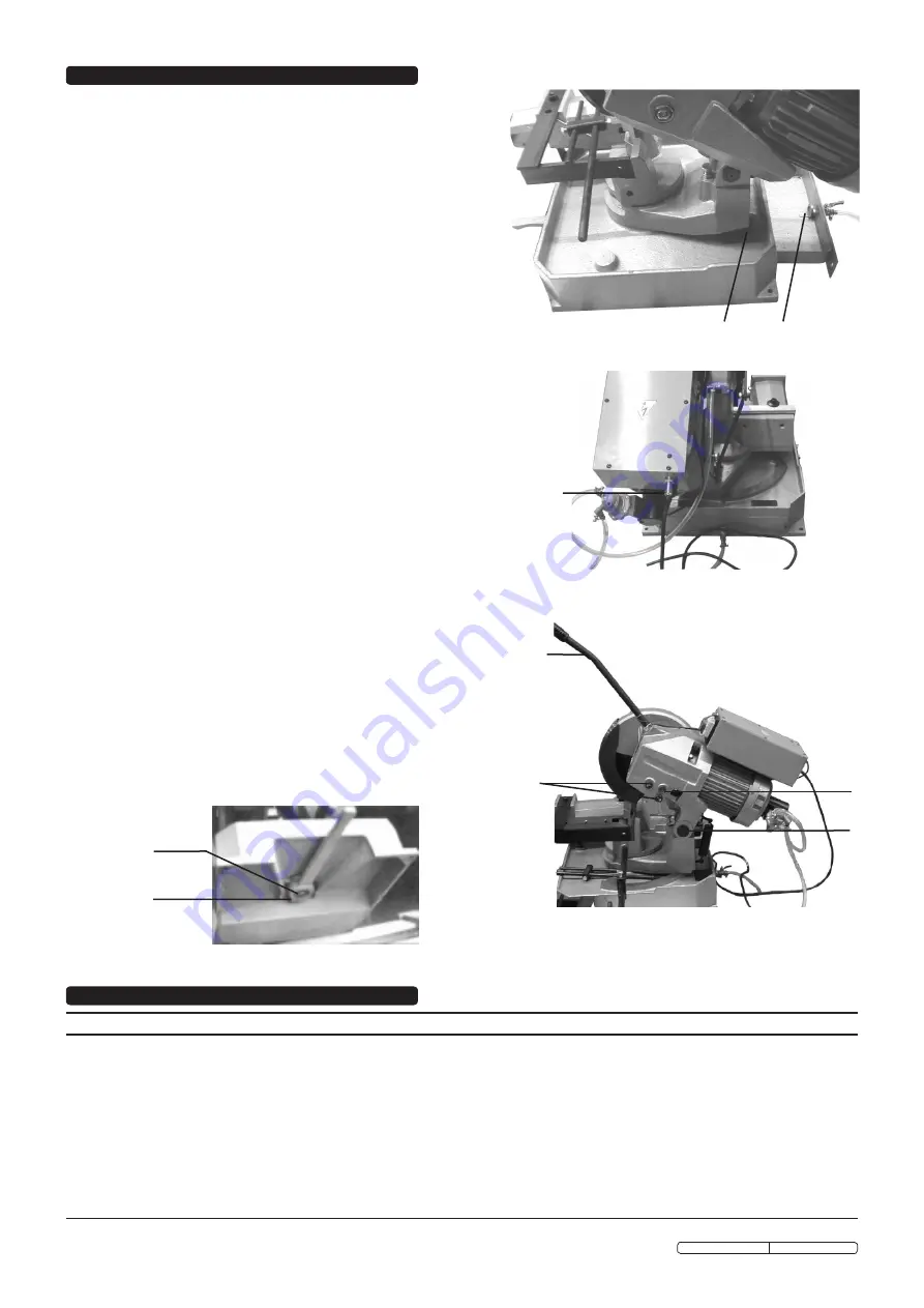
5.2.2. clean the lubricant/coolant filter (fig 9A) and the suction area (fig 9B).
5.2.3. clean and oil the screw and sliding guide of the vice.
5.2.4. clean the blade housing.
5.2.5. Inspect the blade for any sign of wear/damage. replace if necessary
(see section 3.4.
Fitting/replacing a blade
).
5.3.
Monthly maintenance.
5.3.1. check tightness of the screws on the motor, the pump, the vice
and guards.
5.3.2. check that the guards are unbroken.
5.3.3. oil the head hinge pin.
5.4.
Six-monthly maintenance.
5.4.1. change the oil in the reduction unit (Mobil Glycole 30 or equivalent)
as follows.
5.4.2. remove the connecting plug from the electric box (fig 10A) and
unscrew the head control arm (fig 11A).
5.4.3. Drain off the old oil from the drain hole (fig 11B).
Note: Model
SM3154 has two drain holes - both must be opened and drained.
5.4.4. Pour in new oil through the control arm fixing point - oil level
must reach the mark within the glass (fig 11c). Be sure to
maintain the head in a horizontal position throughout the
procedure.
5.4.5. reattach the head control arm and the connecting plug.
5.4.6. switch on the saw and test the operation of the emergency stop button.
5.5.
loose head
: should the hinge become loose, tighten the screws
(fig 11D) being sure not to overtighten.
5.6.
locking lever
: should the locking lever become loose and
ineffective, slacken the screw (fig 12B) on the lever, hold the bush
(fig 12A) in position, turn the lever to the left and tighten the screw.
5.7.
lubricating coolant pump
.
5.7.1. should the pump need replacing, detach the coolant tubes and
remove the fastening screws.
5.7.2. replace the pump (see parts list item sM2504 #90, sM3154 #128)
taking care to keep the driving stem centred on the drive shaft
bearing.
5.7.3. tighten the fastening screws and reconnect the coolant tubes.
A
B
fig 9
fig 10
A
A
B
fig 11
c
D
A
B
fig 12
6. tROUBleSHOOtING
fAuLt
ProBABLE cAusE
rEMEDY
tooth breakage
Advance too fast.
Wrong cutting speed.
Wrong tooth pitch.
Low quality blade.
Ineffective gripping of the part in the vice.
Previously broken tooth left in cut.
cutting resumed on a groove made previously.
Insufficient lubricating coolant or wrong emulsion.
sticky accumulation of material on the blade.
Decrease advance, exert less cutting pressure.
change blade speed and/or diameter.
choose a suitable blade.
use a high quality blade.
check vice and ensure part is held securely.
completely remove all foreign objects from the
cut.
turn the part and begin the cut elsewhere.
check level in coolant tank. Ensure that there are
no blockages preventing the transfer of coolant.
check the mix of lubricating coolant and choose
a better quality blade.
Original Language Version
sM2504, sM3154 Issue: 4 - 07/01/10


