WARNING!
Disconnect the tool from the air supply before changing the disc, servicing or performing
maintenance. Replace or repair damaged parts. Use genuine parts only. Unauthorised parts may be
dangerous and will invalidate the warranty.
5.1.
Lubricate the grinder daily with a few drops of good grade air tool oil, such as Sealey ATO/500 or
ATO/1000, dripped into the air inlet before use or dispensed automatically through an air system oiler,
such as Sealey model SA106L or SA2001/L.
5.2.
Clean the tool after use and change the disc when worn or damaged.
5.3.
Loss of power or erratic action may be due to the following:
a) Excessive drain on the air supply. Moisture or restriction in the air line. Incorrect size or type of hose
connectors. To remedy check the air supply and follow instructions in Section 3.
b) Grit or gum deposits in the tool may also reduce performance. Flush the tool with gum solvent
oil or an equal mixture of SAE No 10 oil and kerosene. Allow to dry before use.
If you continue to experience problems, contact your local Sealey service agent.
5.4.
When not in use, disconnect from air supply, clean tool and store in a safe, dry, childproof location.
4.
OPERATING INSTRUCTIONS
5. MAINTENANCE
WARNING! Ensure that you read, understand and apply the safety instructions before use.
4.1. Assembly
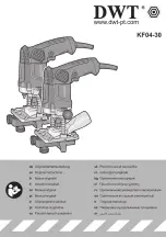
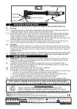
4.1.1. To attach the cutting disc you will need the supplied pressed steel spanner and 4mm allen key, the spanner to
hold the spindle and the allen key to loosen or tighten the socket head cap screw.
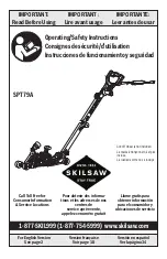
4.1.2. Fit the flange with the 11mm x 0.8mm milled slot on to the spindle, the slot registering with the spanner
flats of the spindle. Place the cutting disc on to the spindle. Place the second flange with the Ø14mm x
0.8mm counter bore on to the spindle with the counter bore adjacent to the cutter face. Hold the
spindle by placing the spanner on the spindle spanner flats. Screw the M6 socket head cap screw into the
spindle and tighten the disc between the flanges with the 5mm allen key (fig.3).
4.1.3. Connect a filtered, lubricated and regulated air supply (fig.2) to the cut-off tool and push down the
safety catch and grip the control valve lever to check that the tool is working correctly.
4.2. Operating
DO NOT
apply excessive pressure, let the cutting disc do the work for you. Start the tool and bring the
disc to the surface to be cut evenly and slowly. Remove the cutting disc from the work surface before
stopping the tool. Regularly check the condition of the disc and always change if worn, cracked or
otherwise damaged.
DO NOT
run the tool away from the workpiece for extended periods as this will shorten the life of the bearings.
WARNING! Use only discs with speed ratings equal to, or higher than, the speed rating of the tool.
NOTE: It is our policy to continually improve products and as such we reserve the right to alter data, specifications and component parts without prior notice.
IMPORTANT:
No liability is accepted for incorrect use of this product.
WARRANTY:
Guarantee is 12 months from purchase date, proof of which will be required for any claim.
INFORMATION:
For a copy of our latest catalogue and promotions call us on 01284 757525 and leave your full name and address, including postcode.
01284 757500
01284 703534
sales@sealey.co.uk
Sole UK Distributor, Sealey Group,
Kempson Way, Suffolk Business Park
,
Bury St. Edmunds, Suffolk,
IP32 7AR
www.sealey.co.uk
Web
Original Language Version
SA2501 Issue: 1 -
14/05/13
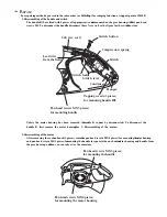
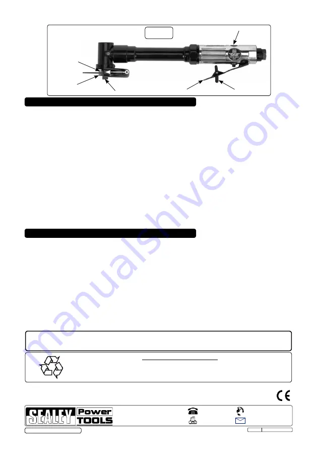
Safety catch
Control valve lever
Throttle valve adjustment
Direction of rotation
fig. 3
Slotted flange
Counter bored flange
Cutting disc
Soc. head cap screw
Environmental Protection.
Recycle unwanted materials instead of disposing of them as waste.
All tools, accessories and packaging should be sorted, taken to a recycle
centre and disposed of in a manner which is compatible with the environment.
Parts support is available for this product. To obtain a parts listing and/or diagram,
please log on to www.sealey.co.uk, email sales@sealey.co.uk or telephone 01284 757500.
© Jack Sealey Limited 2013