


2. INTRODuCTION
C
ontoured composite handle moulded around lightweight aluminium alloy housing reduces effects of chill on operator’s hands and provides
added control. directional, low noise air exhaust can be rotated 360° giving operator added protection. Fitted with safety trigger to prevent
inadvertent operation. Supplied with adjustment spanners.
3. SPECIfICATION
Model No:
.....................................................................
SA70
disk Size ...................................................................... 50mm
Thread Size ............................................................ M6x1mm
Free Speed ...........................................................15000rpm
operating Pressure ...................................................... 90psi
Air Consumption ........................................................... 4cfm
Air Inlet ....................................................................1/4”BSP
Weight ........................................................................... 0.6kg
noise Power/Pressure .................................................186dB
Vibration/ Uncertainty ............................................... 6.56m/s
2
4. PREPARING fOR uSE
4.1.
Air Supply
4.1.1.
Ensure the sander air valve (or throttle) is in the “Off” position before connecting to the air supply.
4.1.2.
You will require an air pressure between 70-90psi, and an air flow according to the specification above.
WARNING!
ensure the air supply is clean and does not exceed 90psi while operating the sander. Too high an air pressure and/or
unclean air will shorten the product life due to excessive wear, and may be dangerous, causing damage and/or personal injury.
4.1.3.
drain the air tank daily. Water in the air line will damage the sander
and will invalidate your warranty.
4.1.4.
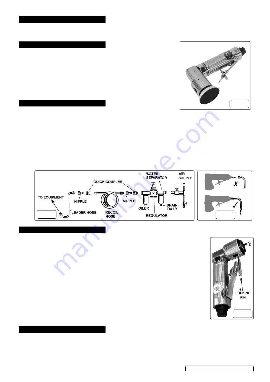
Clean air inlet filter weekly. Recommended hook-up procedure is shown in fig. 2.
4.1.5.
line pressure should be increased to compensate for unusually long air hoses (over 8 metres). The minimum hose diameter should be
1/4” I.d. and fittings must have the same inside dimensions.
4.1.6.
Keep hose away from heat, oil and sharp edges. Check hoses for wear and make certain that all connections are secure.
4.2.
Couplings
Vibration may cause failure if a quick change coupling is connected directly to the air sander. To overcome this, connect a leader
hose to the sander. A quick change coupling may then be used to connect the leader hose to the air line recoil hose. See figs. 2 & 3.
5. OPERATION
WARNING! Ensure you read, understand and apply the safety instructions in Section 1 before use.
5.1.
Assembly
5.1.1.
To fit the backing pad you must first lock the rotating head using the locking pin(fig 4.1). Rotate the head
until the locking hole is visible through the aperture in the outer shroud. Insert the pin as shown in
fig.4.1. Screw the backing pad into the threaded hole in the head (see fig.4.2) and tighten. Remove the
locking pin. Use only discs with speed ratings equal to or higher than the speed rating of the sander.
DO
NOT
use cloth backed sanding discs.
5.1.2.
Connect air supply to sander, press the control valve lever and check that the sander is working correctly.
5.1.3.
The air flow may be regulated by adjusting the regulator valve in the back of the handle.
5.2.
Operating
The sander is designed to provide a combined “rotary” and “random orbit” action. Always use a grit
appropriate for the job. Work progressively from coarse grades to finer grades.
8
DO NOT
go from coarse to fine in one step as it may be difficult to remove swirl marks left by the coarse
grit.
8
DO NOT
apply excessive pressure, let the sander do the work for you. Start the sander and bring the
sanding disc to the work surface evenly and slowly. Move the sander back and forth in overlapping areas.
Remove the sanding disc from the work surface before stopping the sander. Regularly check the sanding
disc for wear, always change if cracked or damaged.
8
DO NOT
allow sander to run in “idle rotation” for an extended period of time, as this will reduce bearing life.
6. MAINTENANCE
WARNING!
disconnect sander from air supply before changing accessories, servicing or performing maintenance. Replace or repair
damaged parts.
Use genuine parts only. Unauthorised parts may be dangerous and will invalidate the warranty.
6.1.
If the air supply does not have an oiler lubricate the air sander daily with a few drops of good grade air tool oil such as Sealey
ATo/1000, dripped into the air inlet before use.
6.2.
Clean the sander after use and change pads when required.
fig.1
fig.2
fig.3
fig.4
SA70 Issue 3 (HF) 31/07/18
Original Language Version
© Jack Sealey limited


