
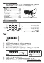
2. INTRODUCTION
Model No. SD005
- 80W Soldering Station with rapid heat up. MCU Controlled temperature calibration. LCD Display screen
showing current temperature and settings. User-friendly menu. Maintains temperatures between 150-480°C.
Capable of pre-setting three frequently used temperatures. Supplied with soldering sponge and soldering iron stand.
3. SPECIFICATION
Model No: ................................................................... SD005
Frequency: .....................................................................50Hz
Heating Element Voltage: ...........................................
26V AC
Power: .............................................................................
80W
Supply: ...........................................................................230V
Temperature Accuracy: ................................................
±10°C
Temperature Range: .........................
150-480°C(302-896°F))
Temperature Stability: .....................
±2°C (in still air, no load)
Tip-to-Ground Resistance: .............................................
< 2Ω
Tip-to-Ground Voltage: .................................................< 2mV
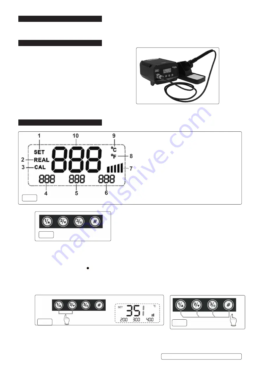
Replacement tip ......................................................SD003ST
Replacement heating element ................................ SD005HE
Replacement iron and cable .....................................SD005IC
Optional extra:
Tip thermometer.............................SD003TT
4. OPERATION
NOTE:
Dampen the sponge wiper before using the soldering station.
4.1.
CONNECTION
4.1.1.
Push the DIN plug attached to the iron lead into the socket on the front panel of the control unit.
4.1.2.
Plug the power cable into the mains power supply after ensuring that it is to the correct standard.
4.2.
SWITCHING ON (fig.1)
4.2.1.
Switch the on/off switch to the ‘
’ setting. Switch is located on the side of the unit.
4.2.2.
The current set temperature will be displayed for 3 seconds.
4.2.3.
After a further 3 seconds, the display will show the real-time temperature of the tip and charging activity if heating is required.
NOTE:
The number of bars shown by the analogue current display (fig.1.7) represent the current being applied to the tip.
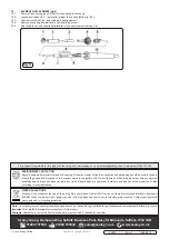
4.3.
TEMPERATURE SETTING (fig.2, fig.3, fig.4)
4.3.1.
The factory set default temperatures stored by buttons: 1, 2 and 3 are 200,300 and 400°C respectively.
4.3.2.
Select button 1, 2 or 3 to initiate required stored temperature.
4.3.3.
With the normal settings applied, the temperature can be adjusted by means of the ▲ and▼ buttons (fig.3).
4.3.4.
The display will go to ‘SET’ and the required temperature will either increase or decrease. Holding the button down will allow rapid
adjustment.
S
D005 Issue 1 19/08/2019
Original Language Version
© Jack Sealey Limited
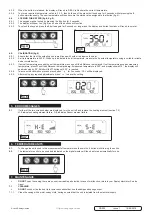
1 . . . . . . . . . . . . . . . . . . . . . . . . . Set Temperature Mode
2 . . . . . . . . . . . . . . . . . . . .Real-Time Temperature Mode
3 . . . . . . . . . . . . . . . . . . . . . . . . . . . . . . Calibration Mode
4 . . . . . . . . . . . . . . . . . . . Temperature Stored: Channel1
5 . . . . . . . . . . . . . . . . . . . Temperature Stored: Channel2
6
. . . . . . . . . . . . . . . . . . . Temperature Stored: Channel3
7 . . . . . . . . . . . . . . . . . . . . . . . Analogue Current Display
8 . . . . . . . . . . . . . . . . . . . . . . . . . . . . . Fahrenheit Values
9 . . . . . . . . . . . . . . . . . . . . . . . . . . . . . . . .Celsius Values
10 . . . . . . . . . . . . . . . . . . . . .Real-Time Tip Temperature
fig.1
fig.2
fig.3
fig.4


