
4.3.5.
When the button is released, the display will revert to ‘REAL’ to illustrate the current temperature.
4.3.6.
To store a required temperature, set as in 3.3.3., then hold one of the preset buttons down for 3 seconds whilst pressing the #
button simultaneously. The new temperature will then become the stored value assigned to that button (fig.4).
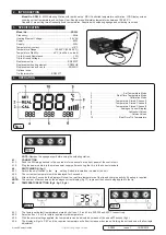
4.4.
LOCKING THE KEYPAD (fig.4, fig.5)
4.4.1.
The keypad may be locked by pressing the # button for 3 seconds.
4.4.2.
The display will show ‘Loc’ (fig.5) and none of the buttons will function.
4.4.3.
To unlock the keypad, press the # button again for 3 seconds or longer and the display and button functions will revert to normal.
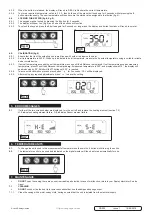
4.5.
CALIBRATION (fig.6)
4.5.1.
Ensure that the tip of the soldering iron is well tinned with solder to disperse the heat.
4.5.2.
Set tip temperature to 350
0
C. When tip is indicated to be at temperature, measure the tip actual temperature using a suitable, reliable
and accurate device.
4.5.3.
If actual temperature exceeds the set temperature press ▲ until the difference is displayed. If set temperature exceeds measured
temperature, press▼ until the difference is displayed
e.g.
if measured temperature is 350°, and display shows 370°, the display will
need reducing by 20°. Scroll will the ▼ button until -20° is reached.
4.5.4.
To access the calibration process press button
‘
‘ for 3 seconds. ‘CAL’ will be displayed.
4.5.5.
After making any required adjustments press
‘
‘ to save the setting.
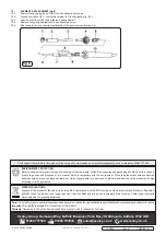
5. ERROR MESSAGES
5.1.
If either of the two screens below are displayed, turn the unit off and replace the heating element (section 7.2).
H-E indicates heating element failure, S-E indicates Sensor element failure.
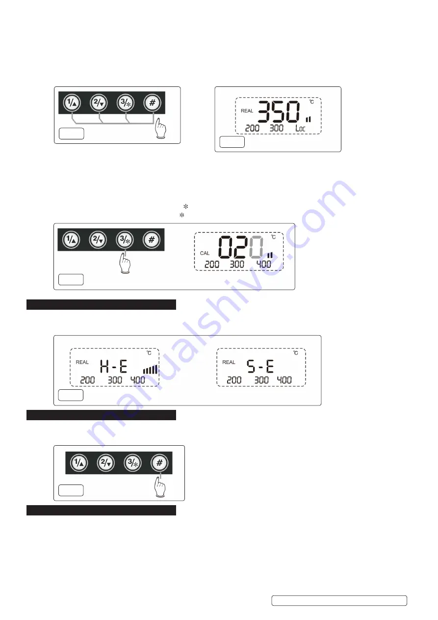
6.
TEMPERATURE UNITS
6.1.
To change the units used in the measurement of temperature hold down the # button whilst turning the unit on.
6.2.
The temperature units to be used and indicated on the digital display will then be stored automatically for use.
7. MAINTENANCE
8
DO NOT
open the casing; there are no user-servicable parts inside. In case of malfunction, return to your Sealey stockist or Service
Agent.
7.1.
CLEANING
8
DO NOT
shock or tap the iron tip to remove excess solder; use the dampened sponge wiper.
7.1.1.
Clean the casing with a moist, soapy cloth, having ensured that the unit is isolated from the electrical supply.
fig.4
fig.5
fig.6
S
D005 Issue 1 19/08/2019
Original Language Version
© Jack Sealey Limited
fig.7
fig.8


