4.4.
Upper blade guide position
4.4.1. The upper blade guide should always be adjusted to about 3mm above the workpiece. To adjust:
Sm1303
- loosen the locking knob and turn the adjustment knob (fig.2.C) to lower the guide to required position. Tighten locking knob.
Sm1304
- simply turn the adjustment knob (fig.3.C) to lower guide to required position.
4.5.
Upper blade guide bearing adjustment
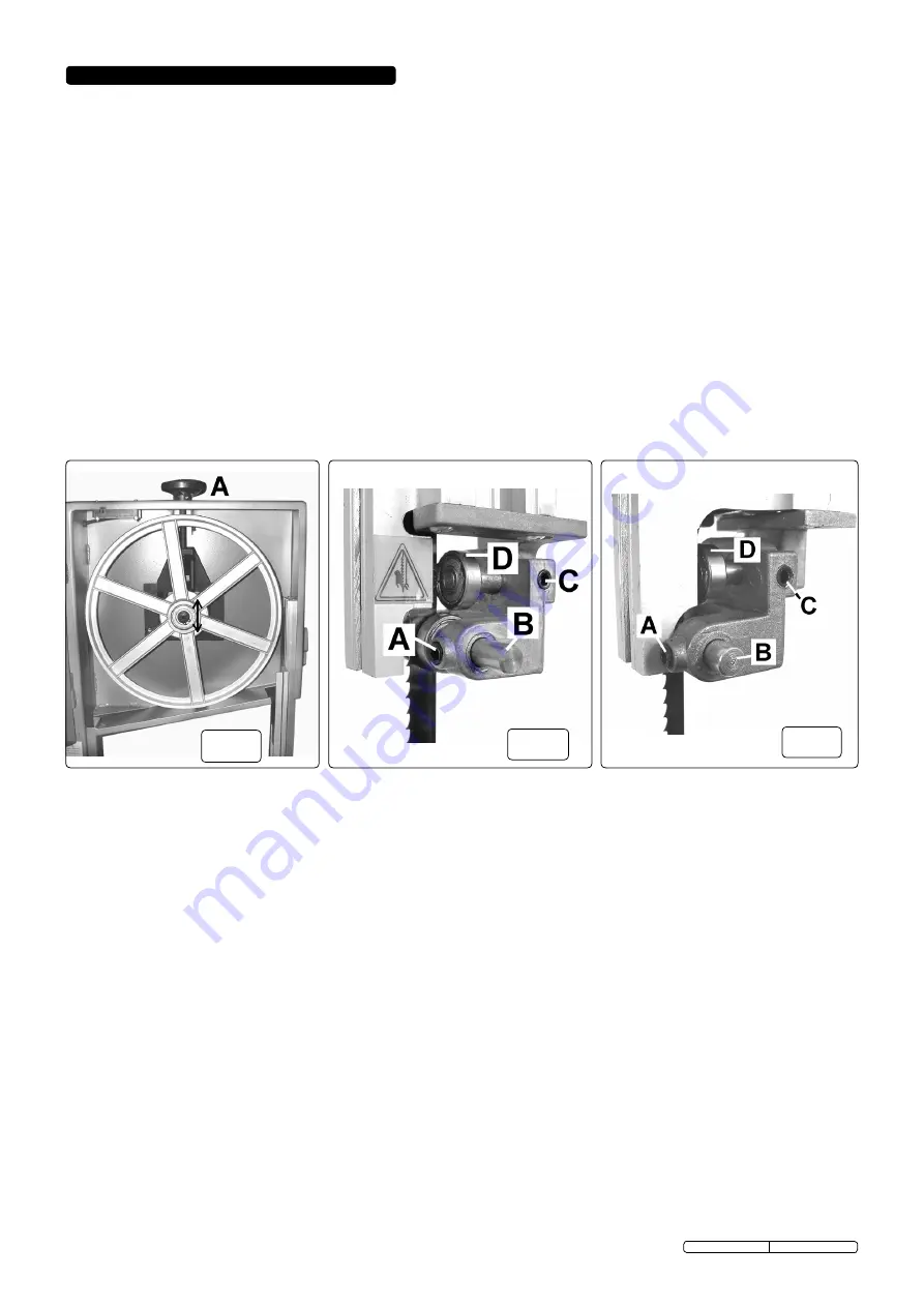
4.5.1. The upper blade side guides prevent excessive sideways movements of the saw blade. They should be adjusted so that they are just
clear of the saw blade. Loosen allen bolts (figs.5 & 6.A) on both sides and press the guides (figs.5 & 6.B) inwards towards the saw
blade. Turn the top wheel twice so that the guides move out slightly and are correctly positioned, then tighten the allen bolts to secure.
Re-check guides for correct positioning.
4.5.2. The upper blade guide rear bearing prevents the saw blade from being pushed backwards when cutting. It should be adjusted so that
it is just clear of the blade (0.75mm). Loosen allen bolt (figs.5 & 6.C) and move the bearing (figs.5 & 6.D) inwards so that it touches
the blade, then adjust it out slightly to just clear of the saw blade. Tighten allen bolt to secure. Re-check for correct positioning.
4.6.
Lower blade guide bearing adjustment
4.6.1. The three lower guides / bearings should be adjusted using the same procedure as for the upper guides / bearings (4.5).
Sm1303:
The two side guides are reached by opening the lower blade cover door, the rear guide is more conveniently reached by
removing the worktable. All three are held in place by allen bolts.
Sm1304:
All three guides are more conveniently reached by removing the work table. The two side guides are held in place by allen
bolts, the rear guide is held in place by an adjustment knob.
Notes: a) Always check and adjust both upper and lower guides at the same time.
b) Carry out these checks/adjustments every time the blade is changed.
c) The blade will be damaged if the teeth contact the guides/guide bearings.
4.7.
mitre gauge
4.7.1. The mitre gauge (fig.1.I), fits in the slot at the front of the work table, it is adjustable through 45° in either direction. Loosen the central
locking knob, adjust and then tighten locking knob.
4.8.
Table Angle
4.8.1. Loosen the knob(s) and adjust table to required angle using the scale as a guide. Tighten knob(s) when in required position.
4.9. Fence
4.9.1. The fence (fig.1.E) is mounted on the table side guide (fig.1.H).
4.9.2. To reposition or remove the fence, push up locking handle (fig.1.G). To refit the fence, slide onto work table from the front or back as
required. Push down handle (fig.1.G) to lock when fence is in required position.
WARNING! ENSURE THAT THE bANDSAW IS DISCONNECTED FROm THE POWER SUPPLY bEFORE ATTEmPTING ANY
ADJUSTmENTS.
4.1.
Changing the blade
4.1.1. Turn the blade cover locks (fig.1 & 3.B) to open the upper and lower blade covers.
4.1.2. Turn blade tension adjustment knob anticlockwise (fig.1 & 3.A) to slacken the blade.
4.1.3. Remove the table side guide by slackening the four bolts and sliding out (SM1304) or the blade retaining bracket by undoing the two
bolts and removing it (SM1303).
4.1.4. Carefully remove the blade.
4.1.5. Install the new blade. Be sure the teeth are pointing downwards and outwards. Refit table side guide / retaining bracket.
4.1.6. Adjust new blade to the correct tension (see 4.2.) and check, and adjust if necessary, tracking (see 4.3.) and blade guide adjustment
(see 4.5. & 4.6.).
4.1.7. Close both blade covers and lock with blade cover locks.
4.2.
Adjusting blade tension
4.2.1. Open the blade covers and check to ensure that blade is centred on both wheel rims (if not, see section 4.3).
4.2.2. Turn the blade tension knob (fig.1 & 3.A) to adjust the blade tension - clockwise to tighten, anticlockwise to slacken.
Correct tension is reached when the blade gives slightly to firm finger pressure at mid-span. Do not over-tighten.
4.2.3. Close both blade covers and lock with blade cover locks.
4.3.
Adjusting blade tracking
4.3.1. Open blade covers and carefully rotate the upper blade wheel (fig.4) clockwise by hand, to determine whether blade is tracking
correctly - blade should be on the centre of each wheel rim.
4.3.2. If adjustment is needed, turn the tracking knob (fig.2.L) whilst continuing to turn the upper blade wheel. Note the effect on
the tracking and continue to turn tracking knob until tracking is correct.
4.3.3. Close both blade covers and lock with blade cover locks.
4. ADJUSTmENTS
fig.4
fig.5
fig.6
Original Language Version
SM1303, SM1304 Issue: 5 - 19/09/13


