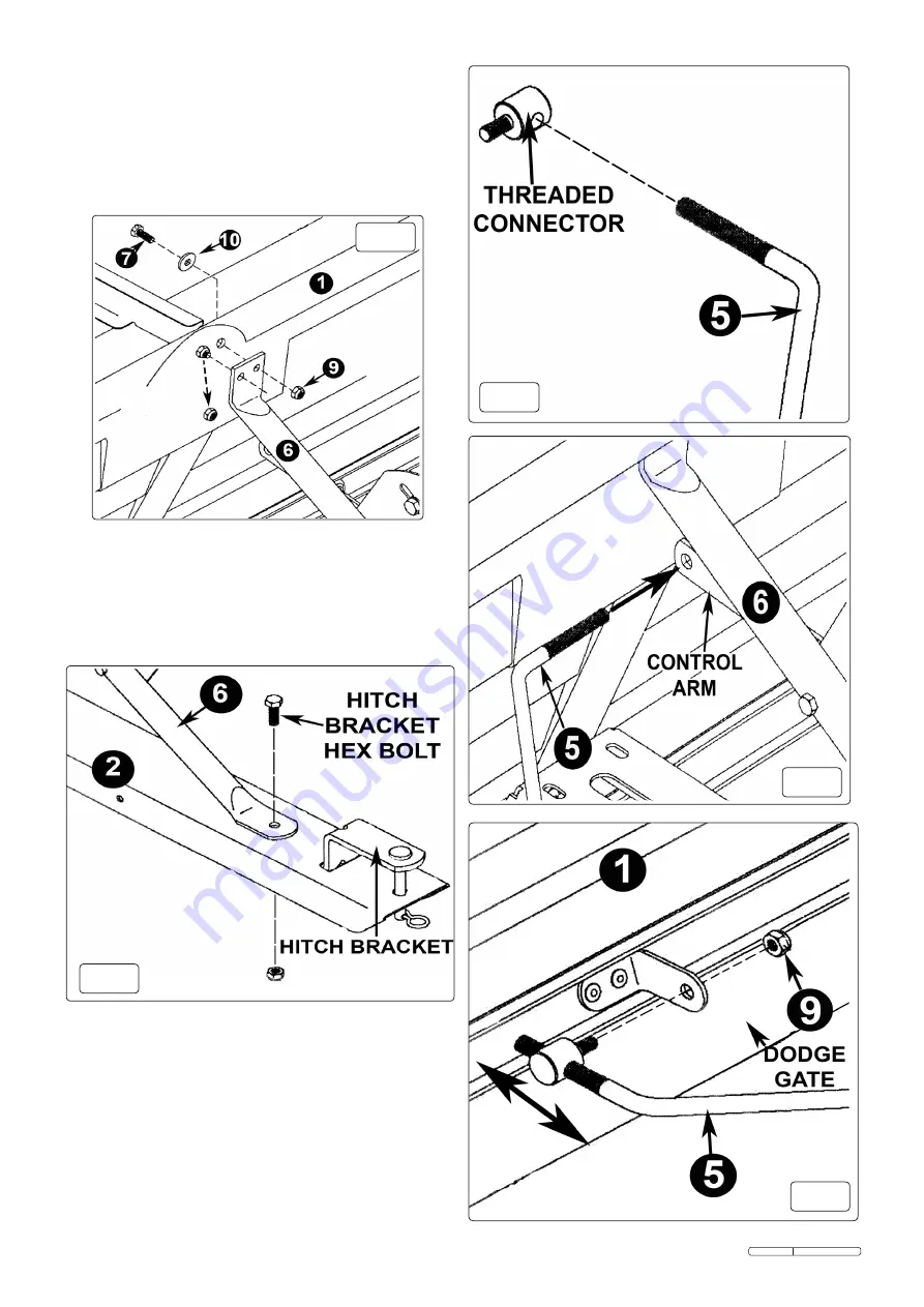
4.7. remove the hex bolt and nut securing the hitch bracket to the
hitch tongue (2). align the loose end of the flow control handle
over the hole and attach to the hitch tongue (2) using the hitch
bracket hex bolt and lock nut as shown in figure 4.
4.8. adjust the position of the flow control handle until it is aligned
with the hitch tongue and the hopper, then fully tighten all the
nuts and bolts used to secure the flow control handle.
4.9.
noting its position on the connecting rod (5), remove one of
the threaded connectors, as shown in figure 5.
4.10. feed the connecting rod (5) through the hole in the control
arm on the flow control handle (6) as shown in figure 6, until
the connecting rod is central in the control arm.
4.11. reattach the threaded connector removed in 4.9. back into its
original position on the connecting rod (5) .
4.12. attach the threaded connectors to the dodge gate brackets on
the hopper (1) using lock nut M6 (9) as shown in figure 7.
Do not over tighten the nuts to allow movement of the flow
control handle mechanism and dodge gate. the position and
range of movement of the dodge gate can be altered by
equally adjusting the threaded connectors up or down the
threaded portions on the connecting rod (5).
Original Language Version
sPD80t Issue: 1 - 21/06/11
4.4.
remove the top lock nut from the front of the hopper (1) as
shown in figure 3.
4.5.
align the top left hand hole of the flow control handle (6) with
the protruding bolt and loosely reattach the lock nut
previously removed in 4.4.
4.6
attach the right hand hole of the flow control valve (6) to the
hopper (1) using hex bolt m6x16 (7), big flat washer Ø6 (10)
and lock nut m6 (9). Do not fully tighten the nuts and bolts at
this stage.
fig.3
fig.5
fig.6
fig.7
fig.4


