3. INSTALLATION
3.1
WINCH INSTALLATION
3.1.1 the winch needs to be mounted onto a steel mounting using the 4 point foot mounting system, in either a horizontal or vertical plane.
3.1.2 The winch needs to be mounted on a flat surface so that the three sections (motor, cable drum and gear housing) are properly aligned.
3.1.3 Before installation ensure the mounting position being used is capable of withstanding the winch weight and the rated capacity.
3.1.4 Use the dimensions in fig.3 to manufacture a steel mounting plate, a minimum of 6mm thick. Fasteners should be high tensile steel,
grade 5 or better. A poorly designed mount may invalidate the warranty.
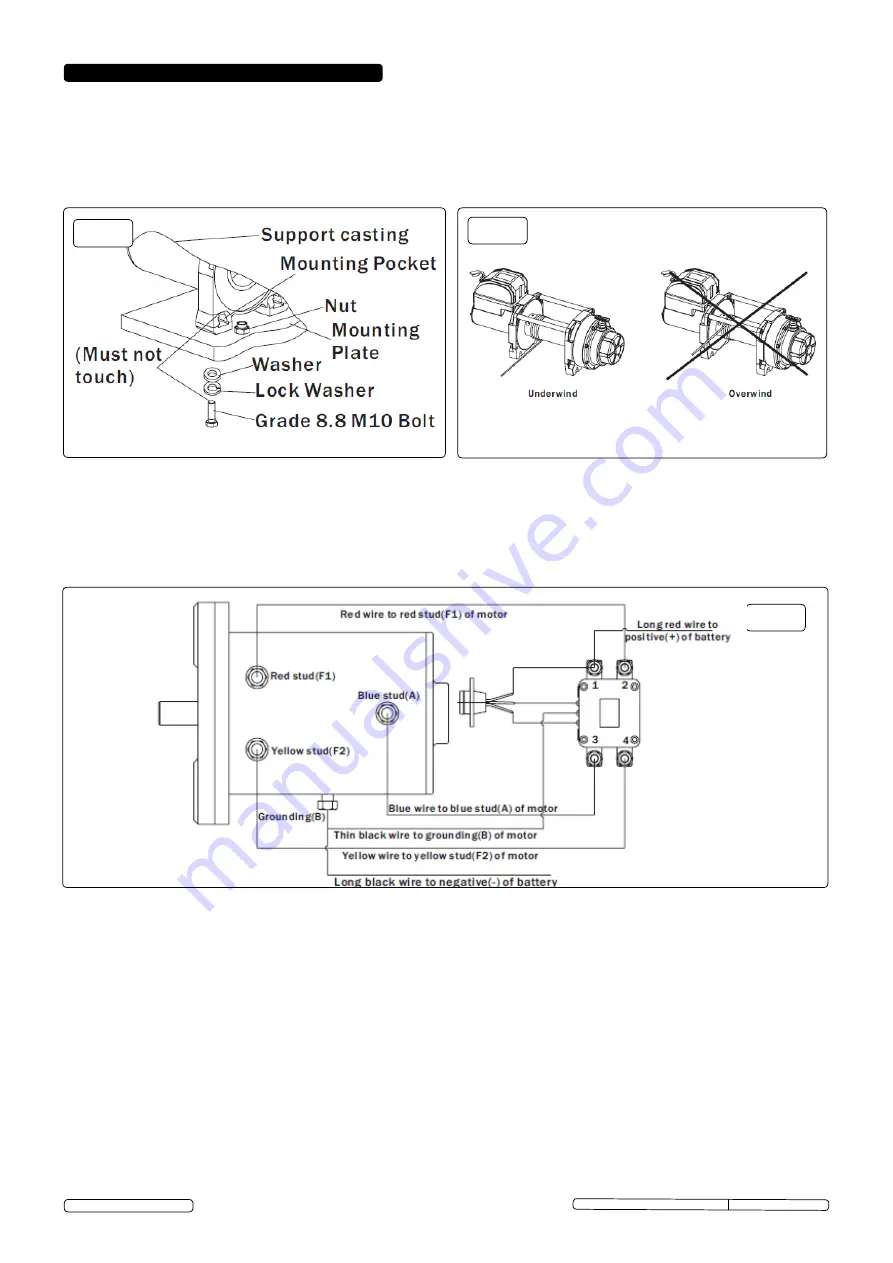
3.1.5 The winch should be secured to the mounting with grade 8.8 M12 bolts and spring washers, see fig.3.
3.2
ELECTRICAL INSTALLATION (Refer to fig.6)
WARNING!
this winch works on standard automotive 12V Dc only, never connect this winch to a 230V mains as solenoid burnout or
fatal shock may occur.
for normal self-recovery work, your existing electrical system is adequate. A fully charged battery and proper connections are essential.
run the vehicle engine during winch operation to keep the battery charged. Pay close attention to the electrical connections below,
ensure that they are made correctly.
NOTE: For
best performance a battery with 440 cold cranking ampere capacity and a 60 amp alternator are the minimum
recommended power source. If the winch is in heavy use, an auxillary battery and heavy duty alternator with isolator are recommended.
Original Language Version
© Jack sealey Limited
Fig.5
Fig.6
WARNING!
Make sure the battery is disconnected.
3.2.1 connect the red wire to the red stud (f1) of the motor and terminal 2 of the relay.
3.2.2 connect the yellow wire to the yellow stud (f2) of the motor and terminal 4 of the relay.
3.2.3 connect the blue wire to the blue stud (A) of the motor and terminal 3 of the relay.
3.2.4 connect the thin black wire to the earth (B) of the motor.
3.2.5 connect the long black wire to the motor earth (B) and the negatve (-) terminal of the battery.
3.2.6 the long red wire will be connected to the positive (+) terminal of the battery,and terminal 1 of the relay, but leave it disconnected from
the battery for the time being.
NOTE:
Your battery must be kept in good condition. Make sure the battery cables are not drawn across any surfaces which could
possibly damage them. corrosion on electrical connections will reduce performance or may cause a short circuit. Keep all connections
clean especially in the remote control switch and receptacle. In salty environments use silicon sealer to protect from corrosion.
srW2720, srW4300, srW5450 Issue: 1 - 03/06/13
Fig.4


