


Model No: ................................................................................SUpERMIG180.V3
Welding Current: .....................................................................................30 - 180A
Wire Capacity - steel: ................................................................................ 5 - 15kg
Duty Cycle: .............100%@56Amps, 75%@65Amps, 60%@73Amps, 15%@145Amps
Cooling System: ..................................................................................... Forced Air
Spot Welding timer ............................................................................................Yes
Gas Type: .................................................................CO², Argon & CO²/Argon mix
Torch: ...........................................................................Euro Non Live - BINZEL ®
Power Input ............................................................................................. 230V 1ph
Absorbed power ........................................................................................... 5.7kW
Case size ...................................................................................................... Large
Weight .............................................................................................................45kg
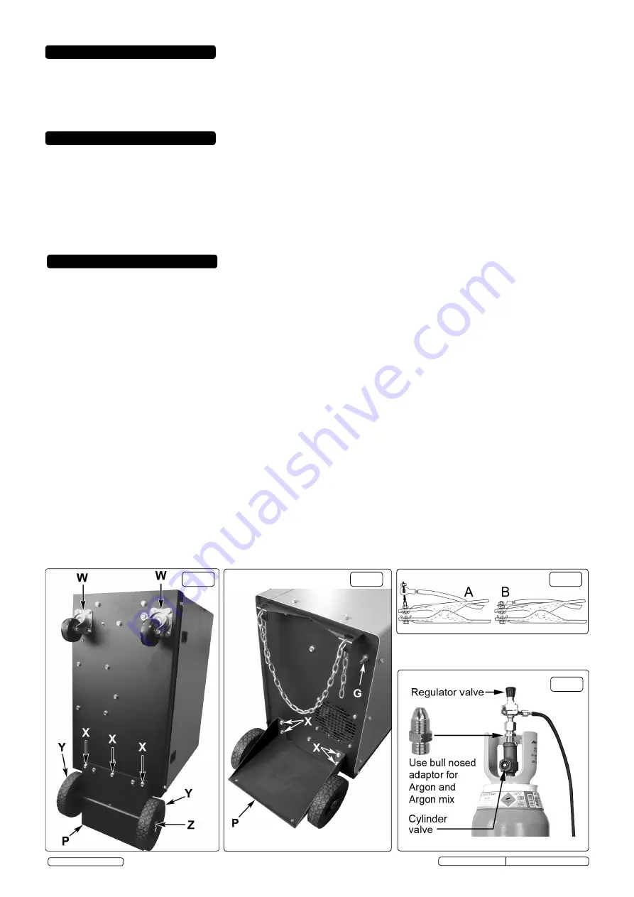
fig.1
4.1.
ASSEMBLING GAS pLATFORM:
(Refer to 'P' in figs.1 & 2) Turn the welder upside down on a smooth non-abrasive surface. The welder should be turned over
by two people as it is very heavy.
4.1.1
The gas platform is held in place with 7 M6 x 10mm bolts requiring a 10mm spanner. The casing has pre-prepared threaded inserts ready to take the fixings.
Place the platform onto the base of the welder with the axle uppermost and fix in place with 3 bolts. See (X) in fig.1 below.
4.1.2
Insert the remaining four bolts through the two fixing flanges laying on the back of the welder. See (X) in fig.2. Finally, tighten all 7 bolts.
4.2.
ASSEMBLING THE WHEELS:
(Refer to fig.1)
4.2.1
Slide a wheel (Y) over each end of the solid axle attached to the gas platform. Slide a washer over each end of the axle and insert a split pin (Z) through the
hole in each end of the axle and bend it over to retain the wheels.
4.2.2
Bolt the two castors (W) to the front end of the base using the 8 bolts provided. The casing has pre-prepared threaded inserts ready to take the fixings. See fig.1.
4.2.3
With the assistance of another person turn the welder the right way up onto its wheels.
4.2.4
The Gas Cylinder Bracket (Item 36) can be found stored inside the wire feed compartment, in the top corner above the wire feed assembly. Remove from this
location and fix to the rear of the machine.
4.3.
ASSEMBLING THE EARTH CLAMp:
(Refer to fig.3) Feed the eyelet on the end of the earth lead through the hole in the clamp arm as shown in fig.3A.
4.3.1
Drop the eyelet over the terminal and firmly fix with the bolt provided as shown in fig.3B.
4.4.
INSTALLING THE GAS CYLINDER.
The welder is designed to accommodate small or medium sized gas cylinders up to a maximum height of 1000mm.
Contact your local Gas dealer for supply.
4.4.1
Place the gas cylinder onto the rear platform of the welder. See fig.2-P. Place one end of the fixing chain into one side of the retaining bracket. Draw the
chain around the cylinder and place it into the slot on the other side of the bracket leaving as little slack in the chain as possible.
4.5
ATTACHING THE REGULATOR.
Whichever gas you are using it is advisable to 'crack' the cylinder valve before attaching the regulator.
This means opening and closing the valve very quickly in order to blow away any dust and dirt that may have accumulated in the gas outlet. Stand to one
side whilst doing this.
4.5.1
CO² GAS.
Ensure that the threads on the gas bottle are undamaged and free of oil and grease before attaching the regulator. (Oil or grease in the presence
of high pressure gases can be explosive). Ensure that the regulator has an undamaged gasket fitted. The regulator will screw directly to the threads on the
gas bottle. Tighten with a spanner.
4.5.2
ARGON GAS OR ARGON MIxTURES.
Cylinders containing Argon gas and Argon mixtures have a female thread and will require the use of a Bull Nose
Adaptor to attach the regulator to the cylinder as indicated in fig.4. Ensure that the threads on the gas bottle are undamaged and free of oil and grease before
attaching the regulator. (Oil or grease in the presence of high pressure gases is explosive). Fit the Bull Nose Adaptor to the cylinder first and tighten with a
spanner. Ensure that the regulator has an undamaged gasket before fitting onto the Bull Nose Adaptor. Tighten with a spanner.
4.5.3 Slide a clip over each end of the gas hose supplied. Push one end of the hose onto the regulator outlet and the other end over the gas inlet spigot
on the back of the welder. See fig.2G. Tighten the clips to ensure a good seal.
4.5.4
Close the regulator valve by turning it anticlockwise before opening the cylinder valve. Stand to one side when opening the cylinder valve.
4.5.5
Set the regulator flow rate to 5-8 litres/min depending on the material to be welded, and whether there are draughts which are strong enough to disturb the
gas flow.
fig.3
fig.2
fig.4
2. INTRODUCTION
3. SpECIFICATION
4. ASSEMBLY/pREpARATION
2.1.
All our Supermig® models are suitable for welding with CO², Argon or CO2/Argon mix. Each uses a Forced Air Cooling System to slow transformer heating in
order to increase duty cycle and a non-live torch to prevent the risk of accidentally striking an arc. All models are supplied with an industrial Argon/CO² regulator.
Welders are illustrated with gas bottles to give an indication of size only; gas is not included. A contract for the supply of gas should be arranged with your local
gas distributor.
2.2. IMPORTANT:
These instructions contain information you require to prepare your machine for welding, together with a maintenance and trouble shooting
section. If you have no previous experience the instructions are not intended to show you how to become a welder . Should you have no experience, we recommend
that you seek training from an expert source. MIG welding is relatively easy to perform, but does require a steady hand and time practising under
supervision with scrap metal as it is only with continued practice that you will achieve the desired results.
Original Language Version
© Jack Sealey Limited
SUPERMIG180.V3 Issue No:5(D) - 11/11/16


