


4.6.
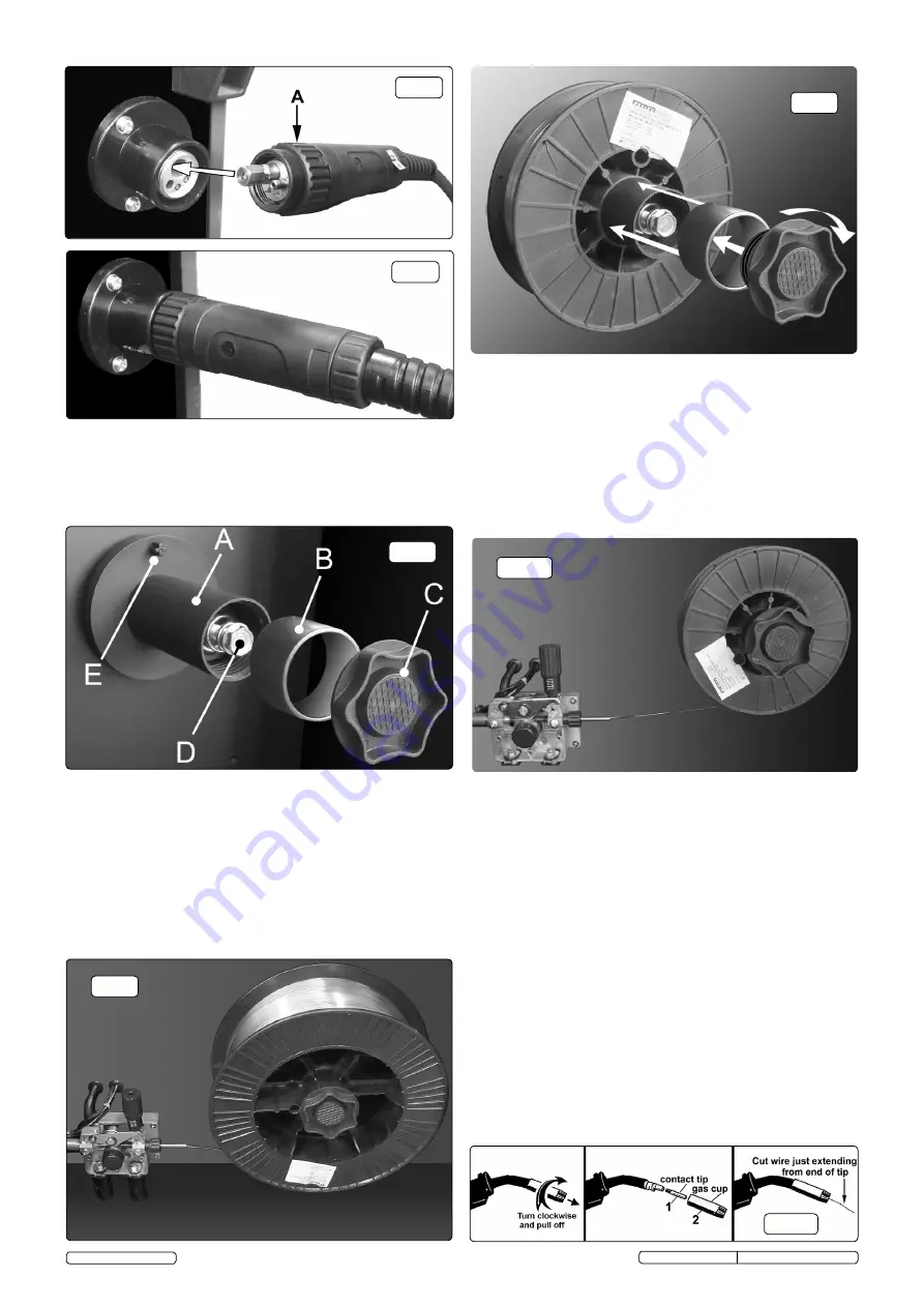
CONNECT THE TORCH CABLE TO THE WELDER.
Align the pins
on the Euro connector with the socket on the welder front panel as
shown in fig.5. Push the connector into the socket and rotate the
locking ring (A) clockwise so that it draws the plug into the socket
as shown in fig.6.
Note: damage to torches and cables is not covered by warranty.
4.7.
FITTING A 15KG REEL OF WIRE.
Ensure that the wire diameter
used, is matched by the correct groove size in the drive wheel and
the correct tip size on the torch as well as the correct torch liner.
Failure to do this could cause the wire to slip and/or bind.
4.7.1
Unscrew the locking knob from the end of the spool holder (see
fig.7C) and remove the spacer (B). The spacer is not required for
15kg reels of wire. Slide the reel of wire onto the spool holder and
ensure that the clutch pin at the back of the spool holder (E)
engages into the guide hole in the wire reel moulding. This will
prevent the wire reel from freewheeling on the spool holder. Ensure
that the wire is coming off the bottom of the reel in the direction of
the wire drive unit as shown in fig.8 below.
4.8.
FITTING A 5KG REEL OF WIRE.
Ensure that the wire diameter
used, is matched by the correct groove size in the drive wheel and
the correct tip size on the torch as well as the correct torch liner.
Failure to do this could cause the wire to slip and/or bind.
4.8.1.
Unscrew the locking knob from the end of the spool holder (see
fig.7C) and remove the spacer. Slide the reel of wire onto the spool
holder and ensure that the clutch pin at the back of the spool holder
(E) engages into the guide hole in the wire reel moulding. This will
prevent the wire reel from freewheeling on the spool holder. Slide
the spacer onto the spool holder and retain it by screwing the knob
into place as shown above in fig.9. Ensure that the wire is coming
off the bottom of the reel in the direction of the wire drive unit as
shown in fig.10.
fig.5
fig.6
fig.7
fig.8
fig.9
fig.10
4.9.
FEED WIRE THROUGH TO TORCH.
Referring to fig.12 open the wire
feed mechanism by pushing the locking/wire tension knob (1) down to
the right allowing the pressure roller carrier (2) to spring up revealing
the feed roller. Ensure that the required feed groove (0.6 or 0.8) is in
line with the wire path. See Section 4.12 on how to reverse or change
the roller.
4.9.1
Release the wire from the reel and cut off any bent portion ensuring
that there are no burrs left on the end of the wire. Keep the wire under
tension at all times to prevent it uncoiling.
4.9.2
Straighten about 40-50mm of wire and gently push it through the
flexible metal sheathed cable (3) and through the 6 or 8mm feed roller
groove and on into the torch cable liner.
4.9.3
Push down the pressure roller carrier onto the wire feed roller and hold
it down. Lift up the locking/wire tension knob so that it enters the slot
in
the pressure roller carrier and snaps into the indent in its top surface.
See fig.13. Rotate the tension knob to a medium setting i.e. between 2
and 3.
4.9.4 Remove gas cup (fig.11-2) and contact tip (1) from end of torch as follows:
a) Take torch in left hand with the torch tip facing to the right.
b) Grasp gas cup firmly in your right hand.
c) Turn gas cup clockwise only and pull it off end of torch tip.
WARNING! do not turn gas cup anti-clockwise, as this will damage
the internal spring.
d) Unscrew copper contact tip (right hand thread) to remove.
4.9.5 Check welder is switched off “0”, and that the earth clamp is away
from the torch tip. Connect the welder to the mains power supply and
set the voltage switch to one.
fig.11
Original Language Version
© Jack Sealey Limited
SUPERMIG180.V3 Issue No:5(D) - 11/11/16


