


4.10. SETTING WIRE TENSION
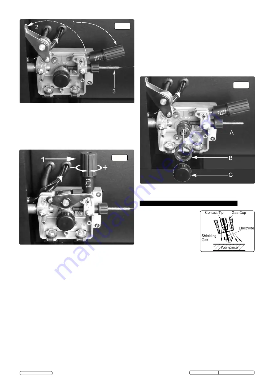
. Adjust the wire tension by rotating the
wire tension knob. Turn clockwise to increase the tension and
anticlockwise to decrease the tension. See (1) in fig13.
IMPORTANT: Too little or too much tension will cause problematic
wire feed and result in poor welding.
4.10.1 Tension between rollers is checked by slowing down the wire between
gloved fingers. If top feed roller skids the tension is correct. Use as
low a tension as possible, too high a tension will disfigure wire and
result in a blown fuse.
4.11. CLUTCH ADJUSTMENT.
Note: It is essential that the clutch is adjusted
correctly.
4.11.1 Once the wire is fed through the torch, switch on the machine and set
the wire speed to maximum.
4.11.2 Depress torch switch and release quickly. If the spool overruns it
indicates that the clutch is too loose.
4.11.3 Tighten the clutch nut located in the centre of the wire spool holder
with a spanner (fig.7-D) and test the machine as above until the wire
stops over running.
Note:
DO NOT
over tighten the clutch as this will cause wire feed
problems and strain the motor.
4.12. TURNING/CHANGING THE DRIVE ROLLER
. (See fig.14) Ensure
that the wire diameter used, is matched by the correct groove size in
the drive wheel and the correct tip size on the torch as well as the
correct torch liner. Failure to do this could cause the wire to slip and/
or bind.
4.12.1 Referring to fig.12, open the wire feed mechanism by pushing the
locking/wire tension knob (1) down to the right allowing the pressure
roller carrier (2) to spring up revealing the feed roller.
4.12.2 Referring to fig.14, loosen and unscrew the black feed roller retaining
knob (C) and put to one side.
4.12.3 The roller carrier (A) is keyed to the main drive shaft and the drive
roller (B) is keyed to the carrier, see below. Place a finger onto the
end of the drive shaft to prevent the carrier moving and slide the drive
roller off the carrier with your other hand.
4.12.4 The size of each wire feed groove is printed on the edge of the roller
on the same side as the groove.
4.12.5 Turn the roller over to use the other groove or use a roller with
different sized grooves as required. The groove to be used should be
positioned furthest away from you to be in line with the drive path.
4.12.6 Check that the key in the carrier (A) is properly seated in its slot.
Ensure that the slot on the inside face of the drive roller (B) is aligned
with the key and slide the roller back onto the carrier.
4.12.7 Screw the black roller retaining knob (C) back on to the end of the
drive shaft and tighten.
4.9.6 Set the wire speed knob to position 5 or 6. Keep the torch cable as
straight as possible and press the torch switch. The wire will feed
through the torch.
4.9.7
When the wire has fed through, switch welder off, unplug from mains.
a) Take torch in left hand, slide the contact tip over the wire and
screw back into place.
b) Grasp gas cup in right hand, push onto torch head and turn
clockwise only. Do not turn gas cup anti-clockwise, as this will
damage the internal spring.
c) Cut wire so that it is just protruding from the cup.
fig.12
fig.14
fig.13
A spool of welding wire is positioned on
the welder’s spool holder and
automatically fed through an insulated
liner in the torch to the tip. The torch
assembly consists of a switch, liner, gas
hose, and control cable. The switch
activates the wire feed roller and the gas
flow. Conversely, releasing the switch
stops the wire feed and gas flow. The
weld current is transferred to the
electrode (the wire) from the contact tip
at the end of the torch. A gas cup fits
over the contact tip to direct the gas flow towards the weld ensuring that the
arc welding process is shielded from oxidising air contaminates. The shielding
gas also assists heating of the weld materials. The torch is connected to the
positive side of a DC rectifier, and the negative clamp is attached to the
workpiece.
IMpORTANT: Should you have no welding experience, we recommend
you seek training from an expert source to ensure your personal health &
safety. Good Mig welding may be achieved only with continued,
supervised practice.
5. 1.
pREpARATION FOR WELDING
IMPORTANT: BEFORE YOU COMMENCE, MAKE SURE THE
MACHINE IS SWITCHED OFF AT THE MAINS. IF WELDING A CAR,
DISCONNECT THE BATTERY OR FIT AN ELECTRONIC CIRCUIT
PROTECTOR. WE STRONGLY RECOMMEND THE USE OF A
Sealey “PROSAF/12V OR 24V IN ORDER TO PROTECT
SOPHISTICATED ELECTRONICS. ENSURE YOU HAVE READ &
UNDERSTOOD THE ELECTRICAL SAFETY INSTRUCTIONS IN
CHAPTER 1.
5.1.1
Connecting the Earth Lead.
To ensure a complete circuit, the earth lead must be securely
attached to the work piece that is to be welded.
a) Best connection is obtained by grinding clean the point of contact
on the workpiece before connecting the earth clamp.
b) The weld area must also be free of paint, rust, grease, etc.
c) When welding a vehicle, be sure the vehicle battery is
disconnected or fit an Electronic Circuit Protector available from
your Sealey dealer.
5. MIG/MAG WELDING
Original Language Version
© Jack Sealey Limited
SUPERMIG180.V3 Issue No:5(D) - 11/11/16


